Wet Film Thickness vs Dry Film Thickness: Measurement Guide
Understanding the difference between wet film thickness (WFT) and dry film thickness (DFT) is fundamental to controlling coating quality, because every coating specification’s corrosion protection performance is ultimately tied to the cured DFT, while the applicator can only directly control and check the WFT in real time during application. Getting the relationship between the two right, and knowing which gauge to use at which stage, is what separates a coating applied to spec from one that looks fine on the day but fails to deliver its design life.
This guide explains exactly what WFT and DFT measure, how to calculate target wet film thickness from a required dry film thickness using volume solids, the gauge types used for each measurement, and the SSPC-PA2 acceptance procedure used to determine whether a coated structure passes DFT inspection.
This article covers WFT and DFT measurement for liquid-applied protective coatings on steel substrates. It does not cover thermal spray metallizing thickness measurement or powder coating cure film build, which use related but distinct procedures.
What Each Measurement Actually Tells You
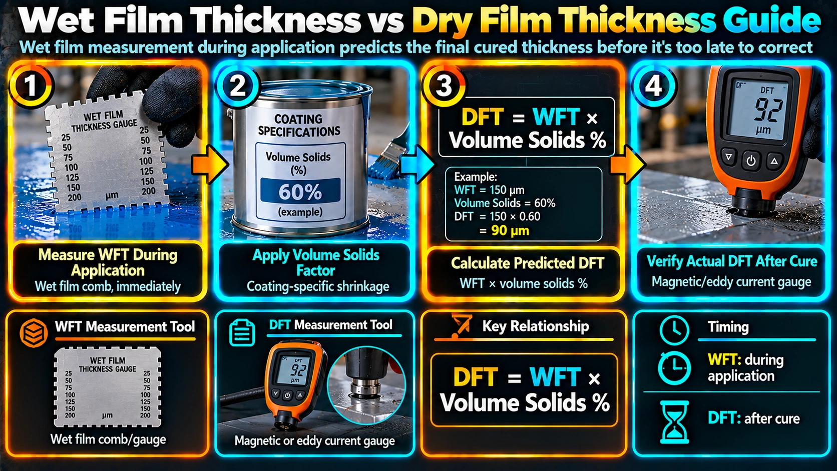
| Parameter | What It Measures | When Measured | Tool |
|---|---|---|---|
| Wet Film Thickness (WFT) | Thickness of the coating film immediately after application, including solvent | Real time, within seconds of application | Wet film comb / gauge |
| Dry Film Thickness (DFT) | Final cured thickness after solvent evaporation and full cure | After adequate cure time per data sheet | Magnetic or eddy current gauge |
WFT measurement matters because it gives the applicator immediate feedback while the coating can still be corrected, whereas DFT can only be measured and confirmed after the film has cured, by which point any deficiency requires a full re-coat rather than a simple adjustment. Skilled applicators check WFT continuously during spray application specifically to avoid discovering a DFT shortfall only after the coating has fully cured.
From WFT to DFT: The Volume Solids Relationship
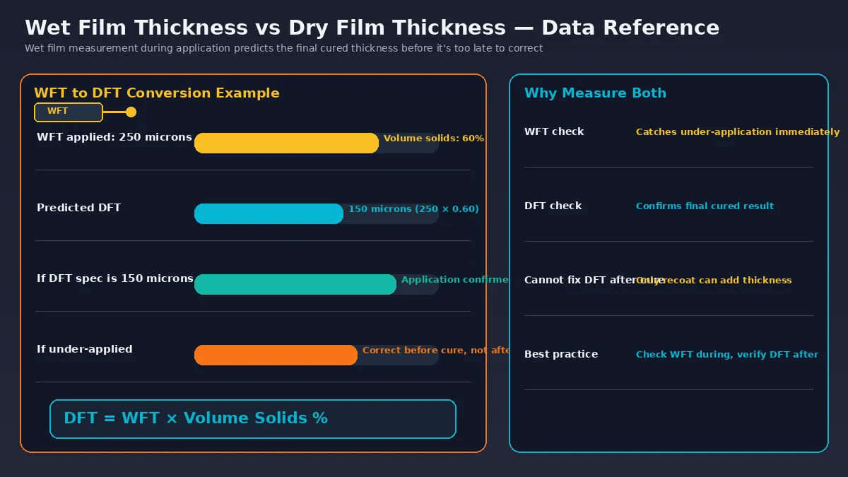
The relationship between wet and dry film thickness is governed by the coating’s volume solids, the percentage of the wet coating that remains as solid film after all volatile solvents evaporate. A coating with a high volume solids percentage loses less thickness during cure than a coating with a low volume solids percentage, so two coatings applied at the same WFT can produce very different final DFT values.
WFT readings are a real-time process control tool for the applicator, not a substitute for final DFT verification, since actual volume solids, evaporation rate, and film shrinkage can vary with temperature, humidity, and thinning. Every coating specification requires DFT as the final accepted measurement, never WFT.
Measuring Wet Film Thickness
A wet film comb, sometimes called a wet film gauge, is pressed perpendicular into the freshly applied coating and withdrawn immediately, before the film begins to level or cure. The thickness is read as the point between the highest tooth still wetted by coating and the lowest tooth left clean. Because the comb disturbs the film at the measurement point, WFT checks should be taken at representative spots that will be re-passed by the spray gun or brush, not left as a permanent gap in the coating.
Check WFT frequently during the early passes of a large panel or structure, not just at the start of the shift, since spray technique, gun distance, and material viscosity can drift as the pot empties, temperature rises, or the applicator’s arm fatigues over a long run.
Measuring Dry Film Thickness
| Gauge Type | Principle | Substrate |
|---|---|---|
| Magnetic pull-off gauge | Mechanical force needed to pull a calibrated magnet off the coated surface | Ferrous (steel) only |
| Magnetic induction gauge (electronic) | Change in magnetic field strength through the coating layer | Ferrous (steel) only |
| Eddy current gauge | Induced eddy currents in a non-ferrous conductive substrate | Non-ferrous (aluminium, etc.) |
| Combination gauge | Automatically detects substrate and switches principle | Both ferrous and non-ferrous |
SSPC-PA2 Acceptance Procedure
| Requirement | SSPC-PA2 Rule |
|---|---|
| Readings per spot | Minimum 5 gauge readings, averaged for the spot value |
| Spots per area | Minimum 3 spot checks per 100 sq ft (9.3 m2) |
| 90% rule | At least 90% of individual spot readings must meet or exceed specified minimum DFT |
| 80% floor | No single spot reading may fall below 80% of specified minimum DFT |
| Maximum DFT | Excess DFT beyond the specified maximum may also require correction per project spec |
On heavily profiled steel, gauge readings taken directly can under-report true coating thickness because the gauge measures relative to the profile peaks. Establish a base metal reading (BMR) on an uncoated panel with matching surface profile and subtract it from coated readings where the project specification requires profile-corrected DFT reporting.
ISO 19840 vs SSPC-PA2
ISO 19840 is the international equivalent to SSPC-PA2 and follows broadly similar statistical acceptance logic but with different specific rules for the number of readings and correction factors applied for surface roughness. Projects specified to European or ISO-based standards should follow ISO 19840 procedures explicitly rather than assuming SSPC-PA2 applies by default, since the two standards can produce different pass/fail outcomes on the same raw gauge data in some cases.
Record coating batch/lot number, ambient temperature and humidity during application, WFT readings taken during application, final DFT spot readings with location references, gauge calibration certificate reference, and pass/fail determination per the governing acceptance standard for every coated panel or structural section.
For multi-coat systems combining zinc-rich primer, epoxy intermediate, and polyurethane topcoat, track and record DFT after each individual coat, not only the final total system thickness, since an out-of-spec intermediate coat can be corrected before the topcoat is applied, but not afterward.
Recommended Reference Material
Digital Dry Film Thickness Gauge
Combination magnetic/eddy current gauge for measuring coating DFT on ferrous and non-ferrous substrates.
View on AmazonWet Film Thickness Comb Gauge Set
Calibrated wet film comb set for real-time WFT checking during coating application.
View on AmazonCoating Inspector Field Handbook
Reference covering WFT/DFT measurement, SSPC-PA2 acceptance rules, and general coating QC procedures.
View on AmazonCoating Thickness Calibration Standards Kit
Certified calibration shims/plates for verifying DFT gauge accuracy before field use.
View on AmazonDisclosure: WeldFabWorld participates in the Amazon Associates programme (StoreID: neha0fe8-21). If you purchase through these links, we may earn a small commission at no extra cost to you. This helps support free technical content on this site.
Frequently Asked Questions
What is the difference between wet film thickness and dry film thickness?
Wet film thickness (WFT) is the thickness of the coating immediately after application, while it still contains solvent and other volatile components, and is measured in real time with a wet film comb or gauge to allow the applicator to adjust technique before the coating begins to cure. Dry film thickness (DFT) is the final cured thickness after all solvents have evaporated, and is the value actually specified in coating standards since it determines corrosion protection performance.
How do you calculate target wet film thickness from a required dry film thickness?
Target wet film thickness is calculated by dividing the required dry film thickness by the coating’s volume solids percentage (expressed as a decimal), so a coating with 60 percent volume solids needing 100 microns DFT requires approximately 167 microns WFT. This calculation assumes no material loss from overspray or application inefficiency, so many specifications add a practical application efficiency factor on top of the theoretical figure.
What is a wet film comb and how is it used?
A wet film comb, or wet film gauge, is a flat metal or plastic tool with a series of notched teeth of varying calibrated depths along its edges. It is pressed into the freshly applied wet coating perpendicular to the surface and withdrawn, and the wet film thickness is read as the point between the highest tooth still coated with wet paint and the lowest tooth that remains clean.
What is the difference between a magnetic and an eddy current DFT gauge?
Magnetic pull-off or magnetic induction gauges are used to measure dry film thickness on ferrous (steel) substrates and rely on the change in magnetic field caused by the coating layer, while eddy current gauges are used on non-ferrous substrates such as aluminium and rely on induced eddy currents instead. Most modern combination gauges automatically detect the substrate type and switch measurement principle accordingly.
How many DFT readings are required per SSPC-PA2?
SSPC-PA2 requires a minimum of five gauge readings averaged per spot check, with a minimum of three spot checks per 100 square feet (approximately 9.3 square metres) of coated area, and the 90/10 rule applies: 90 percent of individual spot readings must meet or exceed the specified minimum DFT, and no single reading may fall below 80 percent of the specified minimum.
Why does surface profile affect DFT gauge accuracy?
Magnetic and eddy current DFT gauges measure from the peaks of the blasted surface profile rather than the true base metal level, which can cause the gauge to under-report actual coating thickness on a rough surface. Many specifications require establishing a base metal reading on an uncoated panel with the same profile and subtracting it from coated readings to correct for this systematic offset, particularly on deep profile surfaces intended for thick-film systems.