Automotive Welding: Robotic Spot and MIG Applications
Automotive welding today is almost entirely a robotic operation, and understanding how robotic resistance spot welding and robotic MIG welding are applied across a modern body-in-white line is essential for any welding engineer working in or supplying the automotive sector. A single passenger vehicle body typically contains thousands of individual spot welds and a smaller but critical number of continuous MIG seams, all completed in a takt time measured in seconds per station rather than minutes per joint.
This guide walks through where each process is used on the vehicle, how the equipment and parameters differ, what quality control looks like on a high-volume line, and the defects and standards that govern acceptance. It is written for welding engineers, QA/QC personnel, and students who need a working understanding of automotive robotic welding beyond the general GMAW process fundamentals.
Whether you are qualifying a new robotic weld cell, auditing a supplier’s body shop, or simply trying to understand why automakers chose one process over another for a given joint, the sections below cover the practical engineering decisions behind automotive robotic welding.
Scope note: This article focuses on resistance spot welding (RSW) and gas metal arc welding (GMAW/MIG) as applied in automotive body and chassis assembly. Laser welding, friction stir welding, and adhesive bonding are referenced for context but are not covered in depth here.
Why Robotic Welding Dominates Automotive Manufacturing
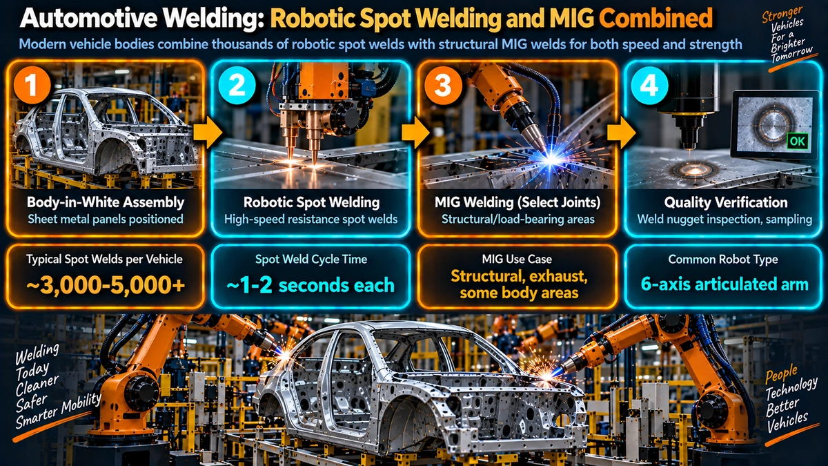
Modern vehicle bodies are assembled at line rates that manual welding simply cannot sustain while holding dimensional and metallurgical consistency. A typical body-in-white structure requires 3,000 to 5,000 resistance spot welds plus additional MIG seams on chassis, exhaust, and structural subassemblies, and this volume has to be repeated tens of thousands of times per month without drift in weld quality.
Robots solve three problems simultaneously: repeatability of electrode force and current delivery, precise and repeatable torch or gun positioning relative to the joint, and full data logging of every weld cycle for traceability. These are the same underlying concerns covered in welding joint design, but automotive volume forces automation of the execution rather than leaving it to operator skill alone.
Robotic Resistance Spot Welding in Body-in-White Assembly
Resistance spot welding remains the primary joining process for automotive sheet steel body structures. A servo-driven welding gun mounted on a six-axis robot clamps two or more overlapping sheets between copper alloy electrode tips, passes a controlled current through the stack, and relies on the contact resistance at the sheet interface to generate localized melting. The molten pool solidifies under continued electrode force to form the nugget.
Servo Guns and Weld Schedules
Nearly all current-generation body shops use servo guns rather than pneumatic guns, because servo motors allow precise, programmable electrode force profiles and tip-to-tip positioning accuracy that pneumatic cylinders cannot match. Each weld schedule programmed into the robot controller specifies squeeze time, weld current and time (often multi-pulse), hold time, and electrode force, and these schedules are tuned per material combination and stack thickness.
Adaptive weld control systems monitor the dynamic resistance curve during the weld cycle itself, adjusting current in real time to compensate for electrode wear, sheet coating variation, and minor fit-up gaps. This is one of the biggest quality improvements over older fixed-schedule timers, and it is worth understanding alongside general welding position and access constraints that also affect gun reach on a body structure.
Electrode Maintenance
Electrode tip dressing is scheduled on a fixed weld count because tip mushrooming increases the contact area and lowers current density at the interface, gradually shrinking nugget diameter even though the programmed current has not changed. Most lines run automated tip dressers integrated into the robot cell that redress the tip geometry every few hundred welds, with periodic full tip changeouts.
Typical stack: Automotive body panels are commonly 0.6–2.0 mm galvanized or bare mild and advanced high strength steel. Zinc coatings reduce electrode life compared with bare steel and require adjusted current and more frequent tip dressing.
Robotic MIG/GMAW Welding in Automotive Assembly
Where resistance spot welding cannot reach, where the joint needs to be gas- or water-sealed, or where thicker chassis, subframe, and exhaust components are joined, automakers turn to robotic MIG welding. Robotic GMAW uses a continuously fed consumable wire, shielding gas, and a synergic power source to lay down a fillet or lap weld along a programmed path, and the general process is the same one covered in the site’s GMAW welding guide, adapted to the speed and repeatability demands of a production robot cell.
Short-Circuit and Pulsed Transfer
Short-circuit transfer GMAW is common on thinner body panel seams and closure panels because of its low heat input and good gap-bridging ability. Pulsed GMAW is increasingly favored on structural and chassis joints and on advanced high strength steel because it reduces spatter, gives finer control over heat input, and produces a more consistent bead profile at the higher travel speeds robots can sustain.
Cold Metal Transfer for Thin and Mixed-Material Joints
Cold metal transfer variants of GMAW, which mechanically retract the wire during short-circuit droplet transfer, have found a strong niche in automotive for very thin gauge panels and for joining steel to aluminum or galvanized assemblies where minimizing heat input protects coatings and reduces distortion. These processes are typically robot-only given the tight timing control required.
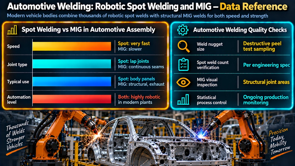
Spot Welding vs Robotic MIG: Where Each Is Used
| Application area | Preferred process | Reason |
|---|---|---|
| Body panel overlap joints (roof, doors, floor pan) | Spot Welding | High volume, thin gauge, fast cycle time, no visible seam required |
| Rocker panels and pillar reinforcements | Spot Welding | Overlapping stampings, structural strength from nugget pattern density |
| Exhaust system and mounting brackets | Robotic MIG | Thicker sections, continuous seal needed, dissimilar wall thickness |
| Chassis and subframe members | Robotic MIG | Higher load joints, thicker material beyond practical spot welding range |
| Fuel tank and fluid-carrying assemblies | Robotic MIG | Continuous seam required for leak-tight sealing |
| Closure panel hem flanges | Both / Hybrid | Spot welds for structure, MIG braze or adhesive for edge sealing and cosmetics |
Materials: Advanced High Strength Steel and Mixed Assemblies
The shift toward advanced high strength steel (AHSS) grades, including dual-phase, TRIP, and boron (press-hardened) steel, has changed how both processes are applied. These grades derive their strength from controlled microstructures that are sensitive to heat input, so both spot welding and MIG welding schedules on AHSS are narrower than on conventional mild steel. Reference material selection logic from the site’s carbon equivalent guidance is a useful starting point when evaluating weldability, even though automotive sheet grades are usually qualified through OEM-specific weld schedules rather than general CE formulas.
Boron steel in particular is often welded in its as-quenched, ultra-high-strength state, and resistance spot welding of this grade requires tighter current control because the narrower plastic range increases the risk of both under-fused and expulsion-prone nuggets on the same schedule. Where aluminum body panels or subframes are joined to steel, self-piercing rivets, flow-drill screws, or adhesive bonding are frequently used instead of fusion welding, since direct fusion welding of steel to aluminum produces brittle intermetallic compounds.
Caution: Never assume a mild steel weld schedule transfers directly to an AHSS or boron steel panel of the same thickness. Heat input windows for these grades are narrower, and an unqualified schedule can produce welds that pass a visual check but fail tensile-shear or peel testing.
Weld Quality Control on the Production Line
Real-Time Monitoring
Every robotic weld cycle on a modern line is monitored electronically. For resistance spot welding, current, voltage, electrode displacement, and force are logged per weld and compared against control limits; deviations trigger an alarm or automatically flag the vehicle body for offline inspection. For robotic MIG, arc voltage and wire feed speed stability, along with seam-tracking sensor feedback, are logged similarly.
Destructive and Non-Destructive Testing
Chisel testing and peel testing on sacrificial coupons remain the standard destructive check for spot weld nugget diameter and full fusion, typically performed on a sampling frequency defined by the OEM’s process control plan. Ultrasonic testing is increasingly deployed directly on production vehicles for non-destructive nugget sizing, giving traceable, non-destructive verification without sacrificing parts. For MIG seams, visual inspection against workmanship standards is supplemented by dye penetrant or radiographic checks on select safety-critical joints, following the same principles covered in the site’s mechanical testing overview.
Common Defects and Troubleshooting
Resistance Spot Welding Defects
- Expulsion: molten metal ejected from the joint interface, caused by excess current, low electrode force, poor fit-up, or worn electrode tips.
- Undersized nugget: insufficient current, excessive shunting through nearby prior welds, or mushroomed electrode tips reducing current density.
- Stick weld / cold weld: the sheets are fused only at the surface without full nugget formation, often from insufficient current or contaminated sheet surfaces.
Robotic MIG Defects
- Porosity: shielding gas contamination or coverage loss, often from robot torch angle changes at high travel speed or from wind disturbance near open bay doors.
- Excess spatter: incorrect arc length, wire stick-out, or transfer mode mismatch for the joint geometry and travel speed.
- Burn-through on thin panels: excess heat input, usually corrected by switching to a lower-energy pulsed or CMT-type transfer mode.
Practical tip: When troubleshooting a new defect pattern on a robotic line, check the electrode tip dress schedule or torch consumable wear first. Most drift in automotive weld quality traces back to consumable condition rather than a change in the underlying weld program.
Robot and End-Effector Technology
Six-axis articulated robots remain the standard platform for both processes, chosen for their reach, repeatability, and payload capacity to carry heavy servo guns. Vision-guided seam tracking and laser displacement sensors are now common additions on MIG welding cells, allowing the robot to adjust its programmed path in real time to compensate for part-to-part variation in stamped panel fit-up, similar in principle to weld joint documentation that specifies nominal geometry but must tolerate real-world variation.
Collaborative robots, or cobots, have started to appear in lower-volume and flexible assembly cells, particularly for MIG welding smaller subassemblies where changeover speed and human-robot proximity are valued over the raw throughput of a large fenced robot. High-volume body-in-white lines, however, remain dominated by large six-axis robots operating inside fenced or light-curtain-protected cells because of the speed and payload these applications demand.
Safety and Compliance in Robotic Welding Cells
Robotic welding cells are designed around layered safety systems: fenced or light-curtain perimeters, interlocked access doors, safety-rated PLCs, and emergency stop circuits that comply with ANSI/RIA R15.06 for industrial robots in the United States, alongside OSHA 1910 requirements covering arc welding hazards, electrical safety, and machine guarding. Fume extraction is integrated directly at or near the torch on MIG welding cells, and zoning controls limit operator exposure to arc flash and UV radiation during maintenance access.
Weld schedule qualification records, consumable certifications, and periodic destructive test results form the QA/QC documentation trail that automotive quality systems such as IATF 16949 require alongside general welding consumable identification practices familiar from other fabrication sectors.
Industry Trends: Automation, Data, and Adaptive Control
The clearest trend across automotive robotic welding is the move from fixed weld schedules toward adaptive, data-driven control. Weld monitoring systems now feed production data into plant-wide analytics platforms, enabling predictive maintenance on electrode tips and torch consumables before defects appear rather than reacting after a quality escape. Machine vision is also expanding beyond seam tracking into automated post-weld inspection, reducing reliance on manual visual checks for surface-level defects.
Electric vehicle production has introduced new joining challenges, particularly around battery tray assemblies that combine aluminum extrusions, steel brackets, and sealing requirements that favor a mix of laser welding, robotic MIG, and mechanical fastening over pure resistance spot welding, reinforcing the trend toward multi-process robotic cells on a single line.
Robotic Welding: Systems and Applications
Covers robot integration, end-effector design, and process control for resistance and arc welding cells.
View on AmazonResistance Welding Manual
Reference text on resistance spot welding theory, electrode design, and weld schedule development.
View on AmazonGMAW Welding Handbook
Practical guide to short-circuit, pulsed, and spray transfer GMAW parameters and troubleshooting.
View on AmazonAutomotive Body Manufacturing Engineering
Overview of body-in-white assembly processes, materials, and joining technology selection.
View on AmazonDisclosure: WeldFabWorld participates in the Amazon Associates programme (StoreID: neha0fe8-21). If you purchase through these links, we may earn a small commission at no extra cost to you. This helps support free technical content on this site.
Frequently Asked Questions
Why do automakers use robotic spot welding instead of manual welding?
Robotic resistance spot welding delivers repeatable weld nugget size and consistent electrode force cycle after cycle, which manual welding cannot match at production line speed. A single body-in-white structure can require 3,000 to 5,000 spot welds, and robots complete this volume with tight cycle times, minimal fatigue-related defects, and traceable weld schedules for every joint.
What is the difference between robotic spot welding and robotic MIG welding in car bodies?
Robotic resistance spot welding joins overlapping sheet metal panels using electrode force and current to form an internal nugget, and is the dominant process for body-in-white structural joints. Robotic MIG or GMAW welding uses a continuous consumable wire and shielding gas to deposit a visible fillet or seam weld, and is used where a spot weld cannot reach, where sealing is required, or where thicker chassis and subframe members need a continuous joint.
Can robotic MIG welding handle advanced high strength steel used in modern car bodies?
Yes, but the welding procedure must account for the narrower heat input window of advanced high strength steel grades such as dual-phase and boron steel. Excessive heat input softens the heat-affected zone and reduces the strength advantage of the base material, so automakers typically favor pulsed GMAW with tightly controlled parameters, and in some cases resistance spot welding or laser welding is preferred over conventional MIG for these grades.
What causes weld expulsion in robotic resistance spot welding?
Expulsion occurs when the molten nugget grows faster than the surrounding metal can contain it, usually from excess current, insufficient electrode force, poor fit-up, or worn electrode tips that have lost their contact area. Expulsion reduces effective nugget diameter and can leave surface pitting, so most production lines monitor weld current and voltage in real time and flag any cycle with expulsion signatures for review.
How is robotic spot weld quality verified on the production line?
Automakers combine destructive and non-destructive methods. Chisel and peel testing on sample coupons verifies nugget diameter and full fusion, while ultrasonic testing is increasingly used for non-destructive nugget sizing directly on the line. Every weld is also logged through adaptive weld control software that records current, voltage, electrode displacement and force for each cycle, giving full traceability back to the specific weld gun and program. See the site’s mechanical testing guide for related destructive test methods.
What safety standards apply to robotic welding cells in automotive plants?
In the United States, robotic welding cells are typically designed to ANSI/RIA R15.06 for industrial robot safety, alongside OSHA 1910 requirements for arc welding, electrical hazards, and machine guarding. Cells use light curtains, interlocked fencing, and safety-rated PLCs to prevent personnel access during robot motion, and arc welding stations add fume extraction and eye protection zoning around the weld path.
Are collaborative robots replacing traditional welding robots in automotive plants?
Collaborative robots, or cobots, are gaining ground in lower-volume and flexible assembly cells where changeover speed and human-robot proximity matter more than raw cycle time. High-volume body-in-white lines still rely mainly on large fenced six-axis robots for resistance spot welding because of their speed and payload, but cobots are increasingly used for MIG welding smaller subassemblies and for tasks like tack welding and finishing where flexibility is valued over throughput.