Galvanic Corrosion in Dissimilar Metal Welds
Galvanic corrosion in dissimilar metal welds is a design problem that a bolted joint can solve with a dielectric gasket but a welded joint cannot fix after the fact — once two dissimilar metals and a filler are fused into one continuous conductive structure, there is no isolation kit available to break the electrical contact that galvanic corrosion needs. That makes filler metal selection, joint design, and, in the worst cases, the decision to avoid direct fusion welding altogether the only real levers an engineer has, and they all have to be pulled before the weld is made.
This guide focuses specifically on galvanic corrosion as it applies to dissimilar metal weld joints — the galvanic series as it applies to common weldable alloys, why welded joints are uniquely exposed compared to mechanical joints, filler metal selection strategy, the area ratio effect in weld and overlay design, and the transition-joint approach used when direct fusion is not practical. For the broader classification of galvanic corrosion alongside other corrosion types, see the corrosion and types guide, which covers the general mechanism this article builds on.
The Galvanic Series for Common Weldable Metals
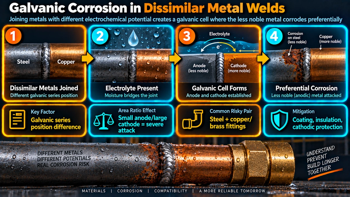
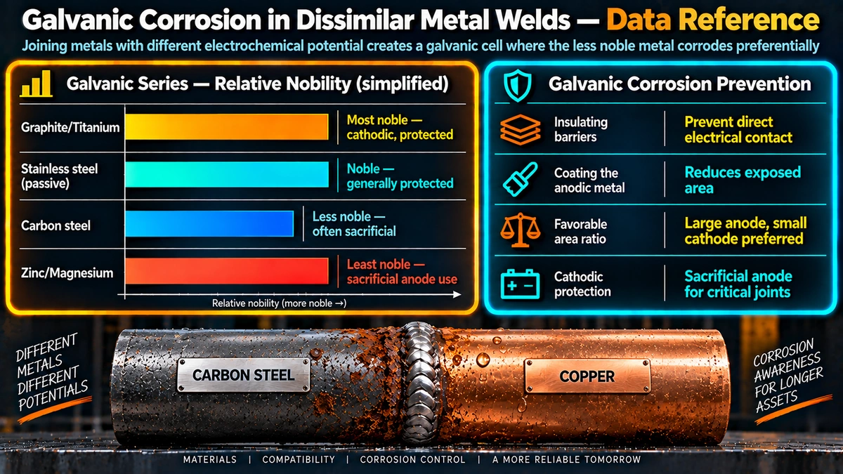
The galvanic series ranks metals and alloys by their relative nobility in a given electrolyte (most commonly seawater, the standard reference environment). Metals higher on the list (more noble/cathodic) are protected when coupled with metals lower on the list (more active/anodic), and the further apart two metals sit, the stronger the driving force for galvanic attack on the more active member.
Why Welded Dissimilar Metal Joints Are Especially Exposed
A bolted or flanged dissimilar metal connection can be electrically isolated with a dielectric gasket, isolating sleeves, and washers, physically breaking the electrical path the galvanic couple needs. See the welding vs bolting guide for when that isolation option is itself a reason to choose a bolted connection over a weld. A fusion-welded joint, by contrast, permanently and continuously bonds the two base metals and the filler metal into one electrically conductive structure — there is no isolation kit that can be retrofitted after the arc has been struck. That makes pre-weld decisions — filler selection, joint geometry, and whether to fuse directly at all — the only points of control available.
Filler Metal Selection Strategy
The standard principle for filler metal selection in a dissimilar metal joint is to choose a filler at least as noble as the more active of the two base metals, so the weld deposit itself does not become the anodic member of the couple. In practice this often means selecting a filler alloyed closer to the more corrosion-resistant base metal rather than simply matching one side — for example, a nickel-based filler (ENiCrFe or ERNiCr-3 type) is commonly used when joining carbon steel to a nickel alloy or high-alloy stainless, deliberately biasing the weld deposit toward the more noble end of the couple.
The Area Ratio Effect in Weld and Overlay Design
The severity of galvanic attack depends heavily on the relative surface areas of the anodic and cathodic members, not just their position on the galvanic series. A small anodic area coupled to a large cathodic area concentrates the same total galvanic current onto a small surface, producing rapid, severe localized attack — the worst-case configuration. The reverse arrangement, a large anode with a small cathode, spreads the same current thinly and corrodes far more slowly.
In practice, this means a narrow weld bead or a small carbon steel fastener that ends up anodic relative to a much larger surrounding stainless or copper alloy structure is a high-risk configuration, even though the same metal pair with reversed area proportions might corrode only slowly. Offshore and marine fabrication specs frequently flag exactly this scenario — small carbon steel fasteners on large stainless or bronze fittings — as a specific design review item for this reason.
Common Dissimilar Metal Weld Systems and Galvanic Risk
| System | Galvanic Risk Level | Typical Approach |
|---|---|---|
| Carbon steel to austenitic stainless | Moderate | Nickel-based or matching stainless filler biased toward the stainless side |
| Carbon steel to copper-nickel | Moderate | Ni-Cu filler, careful area ratio control at small CS components |
| Carbon steel to nickel alloy (Inconel, Monel) | Moderate | Ni-based filler consistent with the more noble base metal |
| Aluminum to steel | High | Explosion-bonded or roll-bonded transition joint — direct fusion generally avoided |
| Galvanized steel to carbon steel (welded) | Low-Moderate | Zinc burns off locally at weld; touch-up coating and sacrificial protection radius considered |
| Duplex/stainless weld overlay on carbon steel | Moderate at dilution zone | Two-layer overlay technique to control dilution at the fusion boundary |
Weld Overlay and Cladding: A Special Case
Weld overlay and clad construction — depositing a corrosion-resistant alloy over a carbon or low-alloy steel substrate — creates a galvanic couple by design at the dilution zone, where the overlay composition grades from the substrate toward the nominal overlay alloy. If the first overlay layer is diluted enough to fall below the corrosion-resistant threshold composition (for example, insufficient chromium in a stainless overlay), that diluted first layer can become a preferentially attacked anodic band beneath a nominally protective second layer. This is the standard justification for the two-layer overlay technique, where the first layer accepts higher dilution and a second layer is deposited to restore full corrosion-resistant composition at the exposed surface.
When to Avoid Direct Fusion: Transition Joints
For metal combinations that are both galvanically incompatible and metallurgically unweldable by direct fusion — aluminum to steel being the standard example, where brittle intermetallic compounds form in addition to the galvanic mismatch — an explosion-bonded or roll-bonded bimetallic transition joint is the standard industry solution. See the welding vs brazing vs soldering guide for how brazing can also sidestep some dissimilar metal fusion problems in lower-strength applications. A transition joint provides a solid-state bonded interface manufactured under controlled conditions, allowing each side to then be welded conventionally to like material, with the galvanic and metallurgical incompatibility contained within a factory-controlled bond rather than a field weld.
Design and Prevention Practices
- Select filler metal toward the noble side of the couple, accounting for expected dilution.
- Avoid small-anode/large-cathode geometry — do not use small carbon steel fasteners or thin sacrificial-grade components against large noble-alloy structures without a protection plan.
- Coat the cathode, not just the anode — coating only the anodic member risks the worst-case small-pinhole area ratio if the coating is damaged.
- Isolate mechanically wherever the joint does not need to be welded — dielectric gaskets, isolation bushings, and non-conductive sleeves at flanged transitions immediately adjacent to a dissimilar weld.
- Use transition joints for combinations that cannot be safely fusion welded, both metallurgically and galvanically.
- Control the electrolyte where practical — drainage design, avoiding standing water at dissimilar joints, and corrosion inhibitor dosing in closed process systems.
Frequently Asked Questions
Why are welded dissimilar metal joints more vulnerable to galvanic corrosion than bolted ones?
A bolted or flanged dissimilar metal connection can be electrically isolated with a dielectric gasket, isolation sleeves, and washers, breaking the electrical contact that galvanic corrosion requires. A welded joint fuses the two metals (and the filler metal) into one continuous electrically conductive structure with no practical way to isolate them, so if the base metals or filler sit far apart on the galvanic series, the couple cannot be broken after the fact — it has to be designed out before welding through filler selection or avoided entirely with a transition piece.
How do I choose a filler metal to minimize galvanic corrosion risk in a dissimilar metal joint?
The general rule is to select a filler metal that is at least as noble (corrosion resistant) as the more active of the two base metals, so the weld deposit does not become the anode in the galvanic couple. In practice this often means selecting a filler alloyed closer to the more corrosion-resistant base metal — for example, a nickel-based filler when joining carbon steel to a nickel alloy — rather than simply matching one base metal’s composition, and always checking the filler manufacturer’s data against the specific service electrolyte.
What is the area ratio effect and why does it matter in weld design?
The area ratio effect describes how the size of the anodic area relative to the cathodic area changes the severity of galvanic attack: a small anode next to a large cathode corrodes far faster per unit area than the reverse arrangement, because the same total galvanic current is concentrated onto a small anodic surface. In weld design this means a thin galvanized coating, a small fastener, or a narrow weld bead that ends up anodic relative to a much larger surrounding structure is a worst-case configuration, even if the same two metals in a large-anode/small-cathode arrangement would corrode only slowly.
Can galvanic corrosion occur even in dry or indoor environments?
Galvanic corrosion requires an electrolyte to complete the circuit, so it does not proceed in a genuinely dry environment. However, atmospheric moisture, humidity-driven condensation, or even a thin film of moisture from occasional washdown or rain intrusion is often enough electrolyte to sustain a slow galvanic reaction over time, which is why galvanic corrosion still shows up on indoor equipment and structural connections that are assumed to be dry.
Is a bimetallic transition joint always necessary for very dissimilar metals like aluminum to steel?
For metal pairs that are both far apart on the galvanic series and metallurgically incompatible for direct fusion welding — aluminum to steel is the classic example — an explosion-bonded or roll-bonded transition joint is the standard practical solution, since it avoids both the intermetallic cracking risk of direct fusion and provides a defined interface where standard corrosion control measures can be applied on each side. Direct fusion welding of aluminum to steel is generally not attempted in production fabrication for exactly these combined metallurgical and galvanic reasons.
Does coating help prevent galvanic corrosion in a dissimilar metal weld joint?
Yes, but only if applied correctly — the standard rule is to coat the cathodic (more noble) member, not the anodic one. If only the anode is coated and the coating develops even a small holiday or pinhole, the exposed anodic area becomes very small relative to the cathodic area, triggering the worst-case area ratio effect and accelerating attack at that pinhole dramatically. Coating the cathode instead, or coating both members fully with a well-maintained system, avoids creating that small-anode condition.
How does weld dilution affect galvanic corrosion risk at a dissimilar metal joint?
Dilution mixes both base metals into the weld pool along with the filler metal, so the actual composition of the solidified weld deposit is not the filler metal’s nominal composition alone — it sits somewhere between the filler and a blend of the two base metals depending on penetration and welding parameters. This matters because a filler chosen to be safely noble relative to both base metals can still end up less corrosion resistant than intended if dilution pulls its composition toward the more active base metal, which is one reason overmatching filler selection and controlled heat input both matter in dissimilar joints.
What is a sacrificial anode and how does it relate to galvanic corrosion at welds?
A sacrificial anode is a deliberately more active metal (commonly zinc, aluminum, or magnesium) electrically connected to a structure specifically so it corrodes preferentially and protects the structure, which is the same galvanic mechanism used constructively rather than as a failure mode. This principle is why galvanized (zinc-coated) steel welds still offer some corrosion protection at small weld-related coating damage areas even though the weld itself typically burns off the zinc coating locally — the surrounding intact zinc coating continues to sacrificially protect the exposed steel at the weld toe within a limited protective radius.
Recommended Reading
Corrosion Engineering (Fontana)
Classic reference with detailed treatment of galvanic corrosion, the galvanic series, and the area ratio effect.
View on AmazonCorrosion of Weldments (Kotecki)
Focused reference on corrosion behaviour of welded and dissimilar metal joints, including filler selection guidance.
View on AmazonASM Handbook Vol. 13: Corrosion
Reference-grade coverage of galvanic series data, area ratio effects, and prevention strategies across alloy systems.
View on AmazonWelding Metallurgy and Weldability of Nickel-Base Alloys
Covers filler selection and dissimilar metal joining practices for nickel alloy transition welds.
View on AmazonDisclosure: WeldFabWorld participates in the Amazon Associates programme (StoreID: neha0fe8-21). If you purchase through these links, we may earn a small commission at no extra cost to you. This helps support free technical content on this site.