Crevice Corrosion: Causes and Prevention
Crevice corrosion is what happens when a narrow, stagnant gap — a gasket face, a backing ring, an incompletely fused lap joint — quietly turns into the most aggressive corrosion site on an otherwise well-selected piece of equipment. It initiates at lower temperatures and in milder environments than the same alloy would need for open-surface pitting, precisely because the crevice geometry itself does most of the initiation work before the environment has to. Fabricated and welded equipment is full of exactly this kind of geometry, which is why crevice corrosion is as much a design and workmanship problem as it is a materials selection problem.
This guide covers the crevice corrosion mechanism in depth, the specific crevice geometries that show up in welded and fabricated equipment, the critical crevice temperature (CCT) concept used to rank materials for crevice-prone service, and the design and workmanship practices that prevent it. For the related open-surface case, see the pitting corrosion guide; for the standardized test method referenced throughout this article, see the ASTM G48 testing guide.
The Crevice Corrosion Mechanism
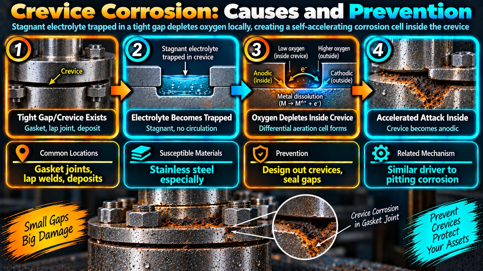
Crevice corrosion follows a self-accelerating sequence rather than a single-step reaction, which is why it is often described as autocatalytic.
Step 1: Oxygen Depletion
Inside a narrow, occluded gap, dissolved oxygen is consumed by the normal reaction that maintains the passive oxide film, and because the gap restricts diffusion, that oxygen cannot be replenished as fast as it is on the freely exposed surface outside the crevice. The oxygen concentration inside the crevice drops progressively below that of the bulk solution.
Step 2: Anode-Cathode Separation
The oxygen-depleted metal inside the crevice becomes anodic relative to the freely exposed, oxygen-rich surface outside, which acts as the cathode. Because the cathodic area (the open surface) is typically much larger than the anodic area (the crevice), the same area ratio effect that governs galvanic corrosion concentrates attack intensely within the small crevice.
Step 3: Acidification and Chloride Concentration
Metal ions dissolving inside the crevice hydrolyze in water, releasing hydrogen ions and lowering the local pH. To balance the resulting positive charge buildup, chloride ions migrate into the crevice from the bulk solution, further concentrating chloride at exactly the location where the passive film is already compromised. This lower pH, higher chloride solution attacks the passive film more aggressively than the original bulk environment ever did, which is why crevice attack accelerates once started rather than reaching a stable rate.
Where Crevices Form in Welded and Fabricated Equipment
| Crevice Source | Typical Location | Best Prevention |
|---|---|---|
| Gasketed flange faces | Bolted piping and vessel connections | Non-porous gasket, full even compression, sealant at edge |
| Retained backing rings | Pipe butt welds | Open-root TIG with purge, or consumable insert instead of solid ring |
| Incomplete penetration / lap fillet joints | Lap and corner joints on plate and pipe | Full-penetration butt welds for corrosion-critical joints |
| Threaded connections | Small-bore fittings, instrument connections | Welded socket or butt-weld fittings instead of threaded, where practical |
| Insulation supports and clips | Insulated piping and vessels | Jacketing integrity, sealed insulation systems, periodic inspection (see CUI mitigation) |
| Deposits, fouling, marine growth | Any wetted surface with poor housekeeping or flow | Cleaning schedule, adequate flow velocity, biofouling control |
| Overlapping plates / doubler plates | Structural and reinforcement details | Seal welding the full perimeter, avoiding intermittent welds on faying surfaces |
Critical Crevice Temperature (CCT): Ranking Materials for Crevice Service
Critical crevice temperature is the minimum test temperature at which crevice corrosion initiates for a given alloy in a standardized test solution, most commonly determined per ASTM G48 Method D (or ASTM F2129 for medical-grade small components). CCT gives a single comparable number for ranking alloys specifically for crevice-prone service, which is a more direct predictor than PREN alone since PREN is calculated from bulk composition and does not account for the geometry-driven initiation advantage a crevice provides.
Design and Workmanship Prevention Rules
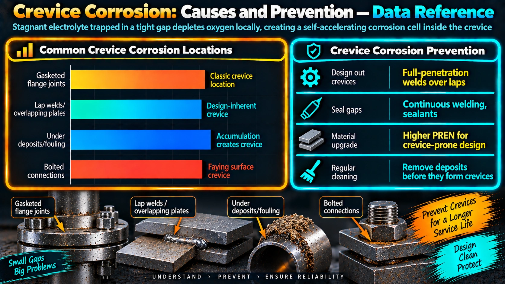
- Use full-penetration butt welds rather than fillet lap joints for corrosion-critical stainless and duplex piping and vessels, eliminating the crevice geometry inherent in lap and incomplete-penetration designs.
- Avoid permanently retained backing rings on corrosion-critical pipe welds — use open-root TIG with correct purge gas control, or a consumable insert ring, instead.
- Specify non-porous, non-wicking gaskets and correctly torque bolting for even, full compression, minimizing residual gap at flange faces.
- Prefer welded connections over threaded fittings at small-bore and instrument connections in crevice-sensitive service.
- Design for drainage — no low points where liquid can stagnate and concentrate chloride during idle periods or shutdown.
- Maintain insulation and jacketing integrity and inspect at known clip and support locations rather than assuming the insulation system is sealed indefinitely.
- Select materials by CCT, not PREN alone, for genuinely crevice-prone service — confirm with welded-coupon G48 Method D data for the actual joint condition, not base metal only.
Frequently Asked Questions
What causes crevice corrosion to start inside a narrow gap?
Crevice corrosion starts because oxygen inside a narrow, stagnant gap is consumed by the normal passive-film-maintaining reaction faster than fresh oxygenated solution can diffuse in to replace it. Once oxygen inside the crevice drops low enough, the metal inside the crevice can no longer maintain its passive film as effectively as the freely exposed surface outside, creating a small anode (inside the crevice) coupled to a much larger cathode (the open surface), which is enough to start localized attack even in an otherwise mild environment.
Why does crevice corrosion get worse once it starts, even without any change in the environment?
Once metal dissolution begins inside the crevice, the resulting metal ions hydrolyze in water to produce hydrogen ions, lowering the pH inside the crevice. Chloride ions also migrate into the crevice to balance the positive charge building up from metal dissolution, so the crevice solution becomes progressively more acidic and more concentrated in chloride over time. This creates an increasingly aggressive local environment that accelerates its own propagation — an autocatalytic process — which is why crevice attack, once initiated, tends to accelerate rather than stabilize on its own.
What is critical crevice temperature and why does it matter for material selection?
Critical crevice temperature (CCT) is the minimum temperature, determined by standardized testing such as ASTM G48 Method D, at which crevice corrosion initiates for a given alloy in a specified test solution (typically ferric chloride). It matters for material selection because it gives a single, comparable number to rank alloys for crevice-prone service — a higher CCT means the material can tolerate hotter, more aggressive service conditions before crevice attack becomes likely, which is directly useful when choosing between 316L, duplex, and super-duplex or 6Mo grades for a specific process temperature.
Can crevice corrosion be completely eliminated through welding technique alone?
Full-penetration butt welds with complete fusion eliminate the crevice geometry that incomplete-penetration and lap/fillet joints create, which addresses crevices caused by the weld joint design itself. However, crevice corrosion also occurs at gasketed flanges, backing rings, bolted connections, and under deposits or fouling, none of which are controlled by weld technique — so welding technique alone reduces but does not eliminate crevice corrosion risk across a full piece of equipment.
Are backing rings a crevice corrosion risk in stainless steel pipe welding?
Yes — a backing ring left in place after welding creates a permanent, tight crevice between the ring and the pipe bore that is very difficult to eliminate once the joint is complete. For corrosion-critical stainless and duplex piping in chloride or otherwise crevice-sensitive service, open-root TIG welding with proper purge, or a consumable/dissolving insert ring, is generally preferred over a permanently retained solid backing ring for exactly this reason.
How is crevice corrosion different from pitting corrosion?
Both are localized attacks on the passive film driven by chloride and share the same underlying autocatalytic acidification mechanism once initiated, but pitting occurs on an otherwise freely exposed, open surface, while crevice corrosion specifically requires a narrow, occluded geometry that restricts oxygen renewal. Because the oxygen-depleted starting condition is already present in a crevice, crevice corrosion generally initiates at lower temperatures and in less aggressive environments than open-surface pitting would require on the same alloy — see the pitting corrosion guide for the open-surface case in detail.
What gasket and bolting choices reduce crevice corrosion risk at flanged joints?
Non-porous, non-wicking gasket materials (solid PTFE rather than compressed fiber types that can wick moisture) reduce the volume of trapped stagnant solution at the gasket face, and fully compressing the gasket with correctly torqued, evenly tightened bolts minimizes the residual gap available to trap solution. Sealant application at the gasket edge, where practical, further restricts fresh chloride ingress into the crevice that does remain.
Does insulation increase crevice corrosion risk on stainless steel equipment?
Yes — insulation supports, clips, and bands create numerous small crevice sites against the vessel or pipe surface, and if moisture penetrates the insulation system, those crevices trap it against the metal for extended periods, combining the crevice geometry with the chloride-concentration mechanism responsible for corrosion under insulation (CUI). This is one of the most common real-world crevice corrosion scenarios in process plants and is why insulation system design and jacketing integrity are treated as corrosion-critical details, not just thermal details.
Recommended Reading
Corrosion Engineering (Fontana)
Classic corrosion textbook with detailed coverage of crevice corrosion mechanisms, the autocatalytic model, and testing.
View on AmazonCorrosion of Stainless Steels (Sedriks)
Authoritative reference on pitting, crevice corrosion, and critical crevice temperature testing for stainless and duplex grades.
View on AmazonASM Handbook Vol. 13: Corrosion
Reference-grade coverage of crevice corrosion, CCT testing methods, and material selection strategy.
View on AmazonCorrosion of Weldments (Kotecki)
Covers how welding condition and dilution affect crevice and pitting resistance at fusion boundaries.
View on AmazonDisclosure: WeldFabWorld participates in the Amazon Associates programme (StoreID: neha0fe8-21). If you purchase through these links, we may earn a small commission at no extra cost to you. This helps support free technical content on this site.