Cathodic Protection: Sacrificial Anode vs Impressed Current
Cathodic protection, delivered through either sacrificial (galvanic) anodes or an impressed current system, is the electrochemical complement to coatings that protects buried and submerged steel structures even where the coating itself has failed or was never applied. Choosing between sacrificial anode and impressed current cathodic protection (ICCP) is a fundamental design decision made early in a pipeline, tank, or offshore structure project, and it depends heavily on electrolyte resistivity, protective current demand, structure size, and access to a reliable power supply.
This guide explains how each system actually works, the anode materials and design calculations involved, and gives clear guidance on when each approach is the better fit. It complements our earlier guide on coating systems for atmospheric, immersion, and splash zone service, since cathodic protection and coatings are almost always designed together, not as alternatives.
This article covers cathodic protection fundamentals for buried and submerged carbon steel structures such as pipelines, tanks, and offshore platforms. It does not cover anodic protection (a distinct technique used for certain stainless steel and titanium process vessels), which works on an opposite electrochemical principle.
How Cathodic Protection Works
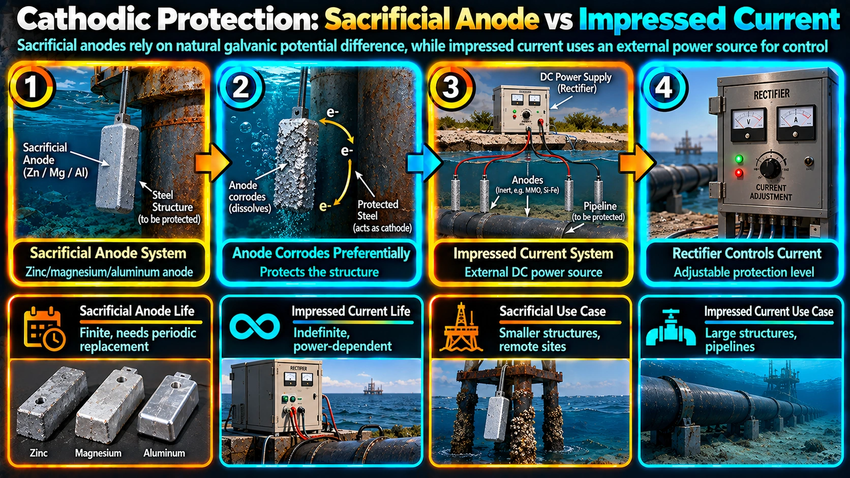
Cathodic protection makes the entire protected structure act as the cathode of an electrochemical cell by supplying it with a surplus of electrons, which suppresses the anodic (metal-dissolving) corrosion reaction at the steel surface. This surplus of electrons can come from a more electrochemically active (less noble) metal that corrodes in the structure’s place, called a sacrificial or galvanic anode, or from an external DC power source that forces current through relatively inert anodes and back to the structure, called impressed current cathodic protection.
Sacrificial (Galvanic) Anode Systems
Sacrificial anode cathodic protection relies on connecting a more electrochemically active metal directly to the structure, allowing the natural potential difference between the two metals to drive protective current with no external power source required. As the anode corrodes over its service life, it must eventually be replaced, and the system’s total current output is fundamentally limited by the anode’s driving voltage and the resistivity of the surrounding electrolyte.
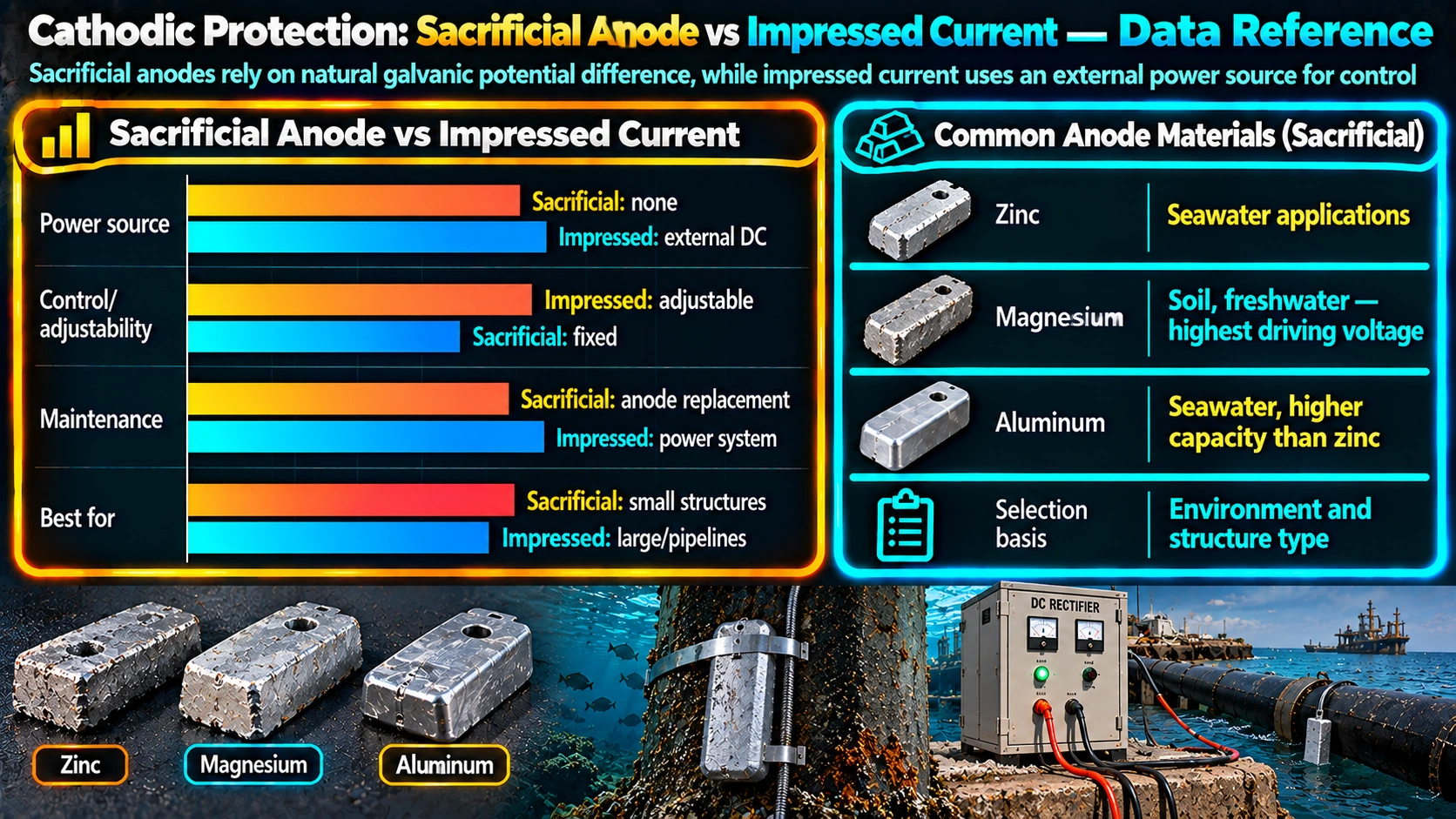
| Anode Material | Typical Environment | Notes |
|---|---|---|
| Zinc | Seawater, some soil applications | Stable, predictable output; lower driving voltage than magnesium |
| Aluminium alloy (Al-Zn-In) | Seawater, offshore structures | High current capacity per kg; widely used offshore |
| Magnesium | Soil, fresh water | Higher driving voltage suited to higher resistivity electrolytes |
Impressed Current Cathodic Protection (ICCP)
ICCP uses an external DC power source, typically a transformer-rectifier unit fed from AC mains or a solar/battery system in remote locations, to force protective current through relatively inert anodes such as mixed metal oxide (MMO) coated titanium or high-silicon cast iron (HSCI). Because the driving voltage is supplied externally rather than limited by galvanic potential, ICCP can deliver substantially higher current output from a smaller number of anodes and is adjustable over the system’s life as protection requirements change.
Comparison Summary
| Factor | Sacrificial Anode | Impressed Current |
|---|---|---|
| Power requirement | None | External AC or DC power source needed |
| Current output | Limited by galvanic driving voltage | High, adjustable via rectifier output |
| Design complexity | Simpler | More complex, requires electrical design |
| Maintenance | Periodic anode inspection/replacement | Rectifier monitoring, anode inspection |
| Interference risk to nearby structures | Low | Higher, requires interference testing/mitigation |
| Typical application | Smaller structures, offshore platforms, ship hulls, tank bottoms | Long pipelines, large tank farms, high-resistivity soil |
| Relative initial cost | Lower for small systems | Higher upfront, more economical for large current demand |
Because ICCP systems impose current into the ground or water over a wide area, they can cause stray current interference on nearby unrelated buried or submerged metallic structures, requiring interference testing and, in some cases, mitigation bonds as part of the system design. Sacrificial anode systems, with their much lower current output, present significantly lower interference risk.
Current Demand Calculation
A well-coated structure with a low coating breakdown factor requires only a small fraction of the protective current that bare steel of the same area would need, which is why cathodic protection is almost always designed as a complement to, not a substitute for, a properly specified coating system.
Verifying Protection: The -850 mV Criterion
Protection level is verified by measuring the structure-to-electrolyte potential with a reference electrode, most commonly a copper-copper sulfate electrode (CSE) for buried structures or a silver-silver chloride electrode for seawater. A widely referenced criterion, documented in NACE SP0169 for buried pipelines, considers steel adequately protected when the measured potential is more negative than -850 mV relative to CSE, though project-specific criteria, IR-drop considerations, and alternative criteria for other reference electrodes should always be confirmed against the governing standard rather than assumed universally applicable.
Cathodic protection current can cause cathodic disbondment, where coating adhesion is lost in a ring around a coating holiday or connection point due to the locally alkaline environment the protective current generates. Coatings intended for use under cathodic protection should be specifically tested and rated for cathodic disbondment resistance (commonly per ASTM G8 or ASTM G95) rather than assumed compatible, and this consideration should feed back into coating system selection for CP-protected structures.
Monitoring and Maintenance
| System Type | Typical Monitoring | Typical Interval |
|---|---|---|
| Sacrificial anode | Structure potential survey, anode visual/weight-loss inspection | Annual survey; anode inspection per design life review |
| Impressed current | Rectifier output check, structure potential survey, anode condition | Rectifier check monthly/quarterly; full survey annually |
Maintain records of anode type, quantity, and installation location, initial and periodic structure-to-electrolyte potential survey results, rectifier output logs where applicable, and any interference test results, all referenced to structure drawings so future maintenance planning can be traced back to original design assumptions.
Cathodic protection system design, including current density selection, anode placement, and interference assessment, is typically performed by a qualified corrosion/CP engineer (such as a NACE CP Level 3 or 4 certified specialist) rather than derived from generic rules of thumb, given the site-specific electrolyte resistivity, structure geometry, and regulatory requirements involved.
Recommended Reference Material
Cathodic Protection Design and Practice Handbook
Covers sacrificial anode and impressed current CP system design, calculations, and field practice.
View on AmazonReference Electrode (Copper Sulfate) Kit
Portable copper-copper sulfate reference electrode for structure-to-electrolyte potential surveys.
View on AmazonCorrosion Control and Protective Coatings Handbook
Reference on combined coating and cathodic protection system design for buried and marine structures.
View on AmazonNACE CP Certification Study Reference
Study reference material for NACE/AMPP cathodic protection technician and specialist certification.
View on AmazonDisclosure: WeldFabWorld participates in the Amazon Associates programme (StoreID: neha0fe8-21). If you purchase through these links, we may earn a small commission at no extra cost to you. This helps support free technical content on this site.
Frequently Asked Questions
What is the main difference between sacrificial anode and impressed current cathodic protection?
Sacrificial (galvanic) anode cathodic protection uses a more active metal, such as zinc, aluminium, or magnesium, that corrodes preferentially to generate protective current without any external power source, while impressed current cathodic protection (ICCP) uses an external DC power source, typically a rectifier, to drive protective current through relatively inert anodes such as mixed metal oxide or high-silicon cast iron. Sacrificial systems are simpler and need no power supply, while ICCP can deliver much higher current output and is adjustable, but requires ongoing power and more complex design.
What anode materials are commonly used for sacrificial cathodic protection?
Zinc anodes are commonly used in seawater and some soil applications, aluminium alloy anodes (often aluminium-zinc-indium) are widely used offshore due to their high current capacity per kilogram, and magnesium anodes are typically used in soil and fresh water applications where a higher driving voltage is needed to overcome higher resistivity. Each material has a different driving voltage, current capacity, and consumption rate suited to different electrolyte environments.
How is the protective current requirement for a structure calculated?
Protective current requirement is calculated by multiplying the total bare (uncoated or coating-breakdown-adjusted) surface area of the structure by a current density value appropriate to the electrolyte and coating condition, typically expressed in milliamps per square metre, with values from published tables or project-specific data based on water chemistry, temperature, and flow velocity. Coated structures require dramatically less current than bare steel because the coating breakdown factor reduces the effective bare area requiring protection.
What is the -850 mV criterion in cathodic protection?
The -850 mV criterion, referenced against a copper-copper sulfate reference electrode (CSE), is a widely used industry benchmark stating that steel is considered adequately cathodically protected when its structure-to-electrolyte potential is more negative than -850 mV. Different reference electrodes and specific project criteria may use different threshold values, and the criterion should always be confirmed against the governing standard, such as NACE SP0169 for buried pipelines.
Can cathodic protection replace coatings entirely?
No. Cathodic protection and coatings are almost always designed to work together, since coatings dramatically reduce the bare steel area requiring protection, which in turn reduces the anode quantity or rectifier current needed to a practical and economical level. Relying on cathodic protection alone without a coating on a large bare structure would require an impractically large anode system or power supply, so the two are complementary rather than alternative corrosion control strategies.
Does cathodic protection affect the coating itself?
Yes, cathodic protection can cause cathodic disbondment, a failure mode where coating adhesion is lost in a ring around a coating holiday or anode connection point due to the alkaline environment generated by the protective current. Coatings intended for use with cathodic protection should be specifically tested and rated for cathodic disbondment resistance, commonly evaluated per ASTM G8 or ASTM G95 test methods, rather than assumed compatible by default.