Creep Rupture Testing for High-Temperature Materials
Last updated:
Creep rupture testing measures how long a metal survives under a constant tensile load at a fixed high temperature, and it produces the rupture-strength data behind boiler, piping and pressure vessel design in the creep range. This guide focuses on how the test is run, while creep mechanisms and stages are covered in a separate article.
Quick Answer: Creep rupture testing loads a machined tensile specimen at constant force and constant temperature until it fractures, recording time to rupture and, if required, creep strain. Repeating the test at several stresses and temperatures gives rupture-strength curves that designers extrapolate to 100,000 hours. ASTM E139 and ISO 204 are the governing test methods.
You will find the procedure, ASTM E139 and ISO 204 requirements, worked calculations, Larson-Miller extrapolation and cross-weld testing of P91 weldments below. It sits alongside the wider mechanical testing of materials overview. Requirements depend on the code edition and contract specification applicable to your project.
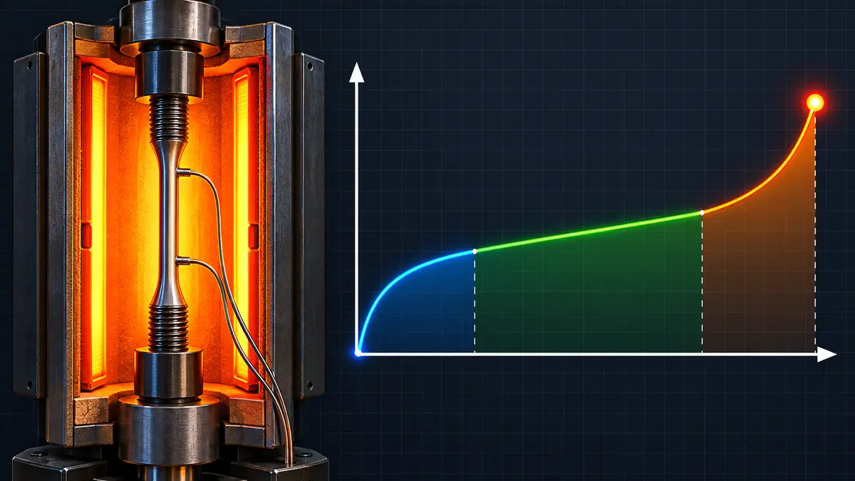
- Creep rupture testing holds a specimen at constant force and temperature until fracture and records time to rupture.
- ASTM E139 and ISO 204 are the main test methods; ISO 204:2023 permits ±3 °C deviation at test temperatures up to 600 °C.
- Stress-rupture tests record fracture time only; creep tests also record strain and give minimum creep rate.
- Larson-Miller extrapolation turns short, hot tests into long-life estimates only while the failure mechanism stays unchanged.
- Cross-weld specimens are needed to expose Type IV cracking in P91 and P92 weldments.
What Is Creep Rupture Testing?
Creep rupture testing is a destructive tension test that measures time to fracture of a metal held at constant load and constant elevated temperature.
The test matters because creep, the slow time-dependent plastic deformation of metal under sustained stress, becomes significant above roughly 0.4 of the absolute melting temperature. Boiler headers, steam piping, furnace tubes and reactor components run in this range for decades, so the room-temperature values in the mechanical properties of metals do not describe them.
A test produces a creep curve in three stages: primary creep with a falling strain rate, secondary creep at a near-constant minimum rate, and tertiary creep that accelerates to rupture. Figure 2 shows where each measured quantity comes from.
What Is the Difference Between Creep, Stress-Rupture and Notched Tests?
The main difference is what is measured. A creep test records extension against time under constant load, giving minimum creep rate and time to a set strain. A stress-rupture test normally records only time to fracture. A notched test adds a circumferential notch to show whether the material is notch weakened or notch strengthened.
| Test type | Measured output | Typical use |
|---|---|---|
| Uninterrupted creep test | Continuous extension, time to a set creep strain, rupture time | Deformation-limited design, minimum creep rate |
| Interrupted creep test | Permanent elongation measured at intervals after cooling | Multi-specimen machines without an extensometer |
| Stress-rupture test | Time to fracture, elongation and reduction of area after fracture | Rupture-strength curves for allowable stress |
| Notched rupture test | Rupture time of a notched test piece against a smooth one | Notch sensitivity of welds and cast alloys Annex C |
Which Standards Govern Creep Rupture Testing?
ASTM E139 and ISO 204 are the two principal test methods for creep and rupture testing of metals, supported by standards for thermocouples, machine verification and extensometers.
| Standard | Issuer | Covers |
|---|---|---|
| ASTM E139 | ASTM International | Creep, creep-rupture and stress-rupture tests of metallic materials, including equipment and reporting |
| ISO 204:2023 | ISO | Uniaxial creep testing in tension; annexes on thermocouples, notched test pieces, uncertainty and extrapolation |
| ASTM E292 | ASTM International | Time-for-rupture notch tension tests |
| ASTM E633 | ASTM International | Use of thermocouples in creep and stress-rupture testing |
| ISO 7500-2 | ISO | Verification of the applied force on tension creep testing machines |
| ISO 9513 | ISO | Calibration of extensometer systems |
ISO 204:2023 is the fourth edition and replaces ISO 204:2018. Obtain the current text from the ISO 204:2023 catalogue page or ASTM International, and state the edition in your purchase order.
How Is a Creep Rupture Test Performed?
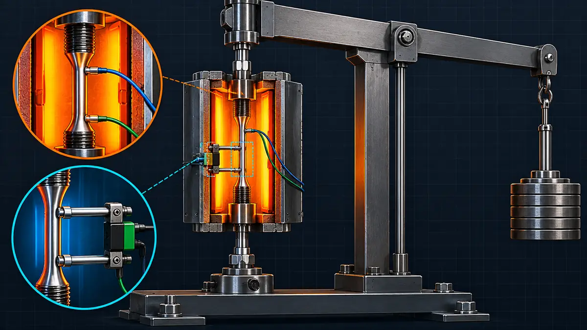
A creep rupture test heats a machined tensile specimen to a set temperature, applies a constant force and records time until fracture. The steps below follow the common practice in ISO 204 and ASTM E139.
- Define the test matrix. Select the material heat, product form, test temperature, stress levels and target durations.
- Machine and measure the specimen. Cut the round specimen from the specified location and orientation, then measure diameter and original cross-sectional area S0 at room temperature.
- Instrument the specimen. Attach thermocouples along the parallel length and fit an extensometer for uninterrupted creep tests.
- Mount with axial alignment. Load the specimen in the machine using grips and joints that keep bending and torsion to a minimum.
- Heat and stabilise. Bring the specimen to the specified temperature and hold until readings are stable within the permitted tolerance before loading.
- Apply the force without shock. Load smoothly to the target force so that initial stress equals force divided by S0.
- Monitor and record. Log temperature, elapsed time and extension continuously, and record any interruption.
- Run to rupture and measure. Record rupture time, then fit the fractured pieces together and measure final length and minimum area to calculate elongation and reduction of area.
What Temperature and Equipment Tolerances Apply?
ISO 204:2023 limits both the deviation from the specified temperature and the temperature variation along the test piece, and the limits widen as test temperature rises.
| Specified temperature T (°C) | Permitted deviation, Tc from T (°C) | Maximum variation along test piece (°C) |
|---|---|---|
| T ≤ 600 | ±3 | 3 |
| 600 < T ≤ 800 | ±4 | 4 |
| 800 < T ≤ 1,000 | ±5 | 5 |
| 1,000 < T ≤ 1,100 | ±6 | 6 |
- Testing machine verified to at least class 1 of ISO 7500-2, with force applied without shock.
- Extensometer of class 1 or better under ISO 9513, gauge length not less than 10 mm, calibrated at intervals not exceeding 3 years.
- Original gauge length generally at least 5 times the specimen diameter.
- Air temperature around the machine within ±3 °C; for interrupted tests, room temperature within ±2 °C during length measurements.
How Are Creep Rupture Results Calculated?
Initial stress equals applied force divided by original cross-sectional area, and ductility after rupture comes from final length and minimum area. Fracture surface examination, covered in fractography in metals, then shows intergranular cracking and cavities.
The example inputs are illustrative. Report the rupture time tu with its temperature and initial stress, for example tu at 600 °C and 120 MPa, so the data point can be plotted directly.
How Is Larson-Miller Extrapolation Used?
The Larson-Miller parameter (LMP) combines temperature and rupture time into one number so that short, hot tests can estimate rupture life at a lower service temperature for the same stress.
The constant C is fitted from data, not assumed for design. Extrapolation fails if the microstructure or damage mechanism changes between test and service conditions. ISO 204 Annex E discusses extrapolation methods, and long-term data on creep-strength enhanced ferritic steels often fall below extrapolations from short tests.
How Does Creep Rupture Testing Apply to Welds and Design Codes?
Cross-weld creep tests and code allowable stresses both depend on rupture data, but they answer different questions: one checks the weldment, the other sets the design stress.
What does a cross-weld specimen reveal?
A cross-weld specimen places base metal, heat-affected zone (HAZ) and weld metal in one gauge length, so the fracture location shows the weakest zone. In creep-strength enhanced ferritic (CSEF) steels such as P91 and P92, failure often occurs by Type IV cracking in the fine-grained or intercritical HAZ. Filler and heat treatment control therefore matter: see the P91 welding requirements, the Ni + Mn limits for P91 and P92 filler metal, the comparison of E9015-B91 versus E9018-B91 electrodes and the PWHT soak time calculator.
ASME Section IX procedure qualification does not include creep rupture tests. Any cross-weld creep requirement comes from the project or purchase specification.
How do design codes use rupture data?
In the creep range, ASME BPVC Section II Part D allowable stresses are limited by time-dependent criteria, including a fraction of the average stress to cause rupture at 100,000 hours and the stress for a creep rate of 0.01 % per 1,000 hours. Verify the exact factors in the edition you use. Power and process piping differ in basis, as explained in the B31.1 and B31.3 allowable stress bases comparison and the ASME B31.3 process piping guide. ASME lists the power piping code on its B31.1 page.
Weld strength in the creep range is reduced through the weld joint strength reduction factor W, which feeds directly into the pipe wall thickness calculator.
What Are the Common Mistakes and Limitations?
Most errors come from treating rupture data as more general than the test conditions allow.
- Mixing constant-force and constant-stress results; ISO 204 notes that they generally differ.
- Letting temperature drift outside the tolerance in Table 3 during long tests.
- Testing base metal only when the specification requires cross-weld specimens.
- Extrapolating far beyond the test duration without checking for microstructural change.
- Assuming a room-temperature Charpy impact test or hardness result predicts creep strength; it does not.
Requirements depend on the code edition and contract specification applicable to your project. Confirm the test standard, edition, specimen type and acceptance criteria with the purchaser before testing. Select laboratories whose accreditation scope, for example under ISO/IEC 17025, lists creep or stress-rupture testing.
Quick Reference: Choosing a Creep Rupture Test
Match the test to the design question, then repeat it across stresses and temperatures.
- Rupture strength curves need at least several stress levels at each test temperature.
- Report tu with temperature and initial stress, plus Au and Zu.
- Keep temperature within Table 3 limits for the full duration.
Key Terms
- Creep
- Slow time-dependent plastic deformation of metal under sustained stress at elevated temperature.
- Rupture time (tu)
- Time to fracture of a test piece held at a specified temperature and initial stress.
- Initial stress (R0)
- Applied force divided by the original cross-sectional area S0.
- Minimum creep rate
- Slope of the creep curve during secondary creep.
- Type IV cracking
- Creep cracking in the fine-grained or intercritical heat-affected zone of CSEF steel welds.
- Larson-Miller parameter (LMP)
- Time-temperature parameter used to extrapolate rupture life.
Frequently Asked Questions
What is the difference between a creep test and a stress-rupture test?
How long does a creep rupture test take?
Should I specify ASTM E139 or ISO 204?
Can Larson-Miller results be used directly for design?
Do welding procedure qualifications include creep rupture tests?
Why do P91 weldments fail in the heat-affected zone during creep?
Conclusion
Creep rupture testing gives the time-to-fracture data that turns a high-temperature alloy into a design allowable. Hold the specimen at constant force and temperature, keep to the ASTM E139 or ISO 204 tolerances, and report rupture time with temperature and initial stress. Use Larson-Miller extrapolation with caution, and test cross-weld specimens where P91 or P92 welds are involved. As a next step, review the ASME P-Number table to see how creep-strength enhanced steels are grouped, or browse the Welding Metallurgy section for related guides.
Standards and References
- ASTM E139, Standard Test Methods for Conducting Creep, Creep-Rupture, and Stress-Rupture Tests of Metallic Materials, ASTM International.
- ISO 204:2023, Metallic materials – Uniaxial creep testing in tension – Method of test, ISO.
- ASTM E292, Standard Test Methods for Conducting Time-for-Rupture Notch Tension Tests of Materials, ASTM International.
- ASTM E633, Standard Guide for Use of Thermocouples in Creep and Stress-Rupture Testing to 1800 F (1000 C) in Air, ASTM International.
- ISO 7500-2, Metallic materials – Verification of static uniaxial testing machines – Part 2: Tension creep testing machines – Verification of the applied force, ISO.
- ISO 9513, Metallic materials – Calibration of extensometer systems used in uniaxial testing, ISO.
- ASME Boiler and Pressure Vessel Code, Section II, Part D – Properties, ASME.
- ASME Boiler and Pressure Vessel Code, Section IX – Welding, Brazing, and Fusing Qualifications, ASME.
- ASME B31.1, Power Piping, and ASME B31.3, Process Piping, ASME.
About This Guide. This guide was prepared by the WeldFabWorld technical team from the standards listed in References. Verify all requirements against the code edition and specification applicable to your project.