Charpy Impact Test: Principle, Procedure, Specimen, Results & Importance
The Charpy impact test, formally known as the Charpy V-notch (CVN) test, is one of the most widely used standardized procedures in materials engineering for quantifying a material’s toughness — specifically, the energy it absorbs before fracturing under a sudden, high-strain-rate load. From pressure vessels to offshore pipelines, from bridge steelwork to cryogenic storage tanks, engineers rely on Charpy test data to confirm that the materials and welds in service can withstand the unexpected shock loads that operational reality inevitably delivers.
This guide covers every aspect of the Charpy impact test: the historical development and physical principle behind it, the precise specimen geometry and machining requirements, the step-by-step test procedure, how to read and interpret the results (including fracture surface analysis and lateral expansion), the critical concept of the ductile-to-brittle transition temperature (DBTT), and how the test is referenced in governing codes such as ASTM E23, ISO 148-1, and ASME Section VIII Division 1, paragraph UG-84. Whether you are a welding engineer qualifying a procedure, a quality inspector reviewing mill certificates, or a student preparing for professional certification, this article gives you a complete, authoritative reference.
The test is also directly relevant to mechanical testing qualification requirements under ASME Section IX and to UG-84 Charpy impact test requirements for pressure vessel fabrication. Understanding the test fundamentals is therefore essential for anyone working to pressure equipment codes.
History and Development of the Charpy Test
Impact testing as a concept predates Charpy himself. S. B. Russell proposed a pendulum-based fracture energy test in 1898, but it was French metallurgist Georges Augustin Albert Charpy (1865–1945) who, around 1901–1905, refined the method, standardized the specimen geometry, and demonstrated its repeatability and engineering utility. His work was contemporaneous with similar efforts by Izod in Britain, but Charpy’s horizontal simply-supported beam configuration proved more amenable to temperature testing and became the internationally dominant method for metals.
The test gained rapid adoption after catastrophic brittle fractures in Liberty ships during World War II revealed how low-temperature brittleness in mild steel could cause sudden, catastrophic structural failure. Post-war investigations made the Charpy test a mandatory qualification requirement in virtually every major structural and pressure equipment code worldwide — a role it still holds today.
ISO 148-1 — Metallic Materials, Charpy Pendulum Impact Test, Part 1: Test Method (International)
EN ISO 148-1 — European adoption of ISO 148-1
ASME Section VIII Div. 1, UG-84 — Impact test requirements for pressure vessels
Physical Principle of the Charpy Impact Test
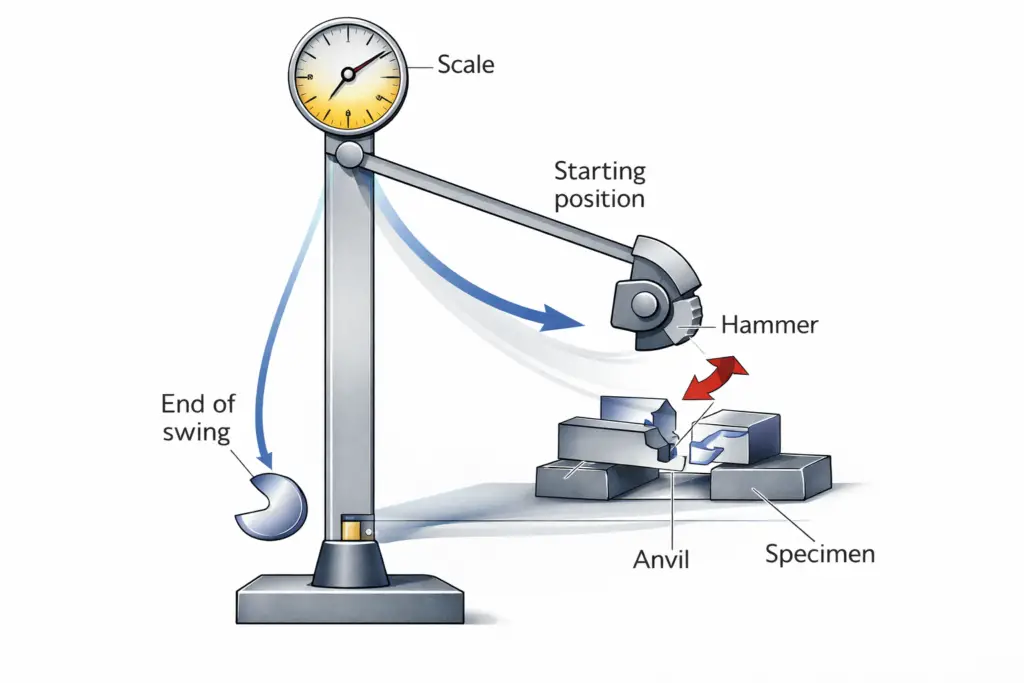
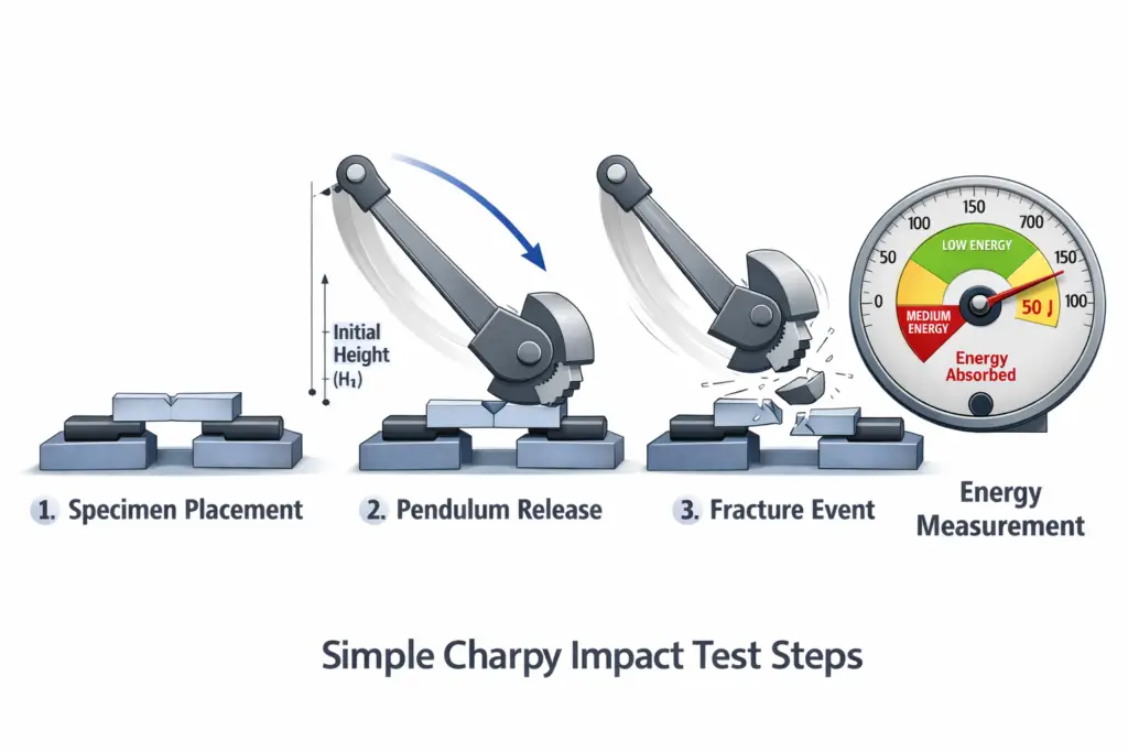
The Charpy test is fundamentally a conservation of energy experiment. A pendulum hammer of known mass is raised to a precisely calibrated initial height, giving it a defined amount of potential energy. When released, it swings down and strikes the notched specimen. If the specimen were absent (or infinitely tough), the pendulum would swing up to the same height on the far side. In reality, the energy absorbed by fracturing the specimen is “missing” — the pendulum swings to a lower height. The difference in potential energy before and after corresponds to the absorbed impact energy.
The Energy Absorption Formula
Modern testing machines calculate and display this value automatically via calibrated dial indicators or digital readouts. The operator simply records the value and, where required, measures the lateral expansion and estimates the percent shear area on the fracture surface.
Charpy Specimen: Geometry and Notch Types
The geometry of the Charpy specimen is precisely defined in ASTM E23 and ISO 148-1 because small deviations in the notch root radius or depth profoundly affect the measured impact energy. All specimens must be machined to tolerance and handled carefully to avoid surface damage that could influence results.
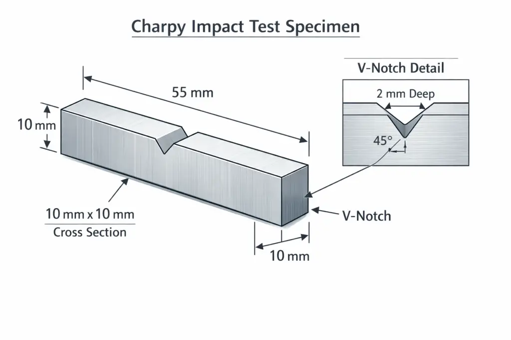
Standard V-Notch Specimen (CVN)
The standard specimen dimensions are:
- Length: 55 mm
- Cross-section: 10 mm × 10 mm
- Notch: 45-degree V-notch, 2 mm deep, 0.25 mm root radius, machined at the mid-length on one face
Sub-Size and Alternative Notch Types
When full 10 mm × 10 mm specimens cannot be extracted (for example, from thin plate, pipe wall, or small-diameter bar), sub-size specimens are permitted. ASTM E23 and ASME UG-84 define requirements and adjustment factors for sub-size specimens:
| Specimen Type | Dimensions (mm) | Notch | ASME Min. Energy Factor | Notes |
|---|---|---|---|---|
| Full-size CVN | 55 × 10 × 10 | V, 45°, 2 mm deep | 1.0 (reference) | Standard for code qualification |
| Sub-size 7.5 mm | 55 × 7.5 × 10 | V, 45°, 2 mm deep | × 5/6 | Reduced energy requirements apply |
| Sub-size 5 mm | 55 × 5 × 10 | V, 45°, 2 mm deep | × 2/3 | Used for thin-wall applications |
| Sub-size 2.5 mm | 55 × 2.5 × 10 | V, 45°, 2 mm deep | × 1/3 | Results have lower confidence |
| Keyhole (KV) | 55 × 10 × 10 | Keyhole 1.5 mm radius | Separate table | Less common; older applications |
| U-Notch (DVM) | 55 × 10 × 10 | U, 5 mm deep, 1 mm radius | Separate table | ISO designation; used in Europe |
Test Equipment and Procedure
Charpy testing is performed on a pendulum impact testing machine — a robust, precision device that must itself be periodically verified and calibrated per ASTM E23 Annex A1 or ISO 148-2. The machine consists of a rigid frame, a pivoting pendulum arm with a striker head, calibrated energy scales, and two precisely positioned anvil supports that hold the specimen.
Step-by-Step Test Procedure
- Machine verification: Confirm the machine has been calibrated within the required interval. Check that the striker geometry (2 mm radius for standard CVN) matches the specimen notch type.
- Specimen conditioning: If testing at sub-ambient temperature, place specimens in a controlled bath (liquid nitrogen, dry ice/solvent, or a chamber) and hold at the target temperature for at least 5 minutes and no more than 10 minutes before transfer to the machine. Transfer time must not exceed 5 seconds (ASTM E23).
- Specimen positioning: Place the specimen horizontally on the two anvil supports, with the notch facing away from the pendulum. Centre the specimen using a centring tool so the striker hits the back face at the notch midpoint.
- Pendulum release: Release the pendulum from its latched starting position (H₁). It swings freely, strikes and fractures the specimen, and continues to rise on the far side to height H₂.
- Read absorbed energy: Record the energy value displayed on the dial or digital readout.
- Fracture surface examination: Retrieve the fractured halves and assess percent shear area (ductile vs brittle fracture appearance) and measure lateral expansion if required.
- Report: Report absorbed energy (J or ft-lb), test temperature, specimen size, orientation, and, if measured, percent shear and lateral expansion.
Specimen Orientation: Longitudinal vs. Transverse
Specimen orientation relative to the rolling or forging direction of the material has a significant effect on measured impact energy. Codes typically specify:
- Longitudinal (L-T): Specimen long axis parallel to the working direction; notch opens in the transverse direction. Generally gives higher toughness values.
- Transverse (T-L): Specimen long axis perpendicular to the working direction. Gives lower, more conservative toughness values and is often required by piping and vessel codes for critical applications.
Always confirm the required orientation in the applicable code or material specification before extracting specimens.
Interpreting Charpy Test Results
Absorbed Energy Values
The primary output is the absorbed impact energy in Joules (J). A set of three specimens is normally tested per ASTM E23 and ASME UG-84 requirements, and the average value is compared against the code-mandated minimum. Individual specimen values must also not fall below a defined lower limit (typically 2/3 of the minimum average).
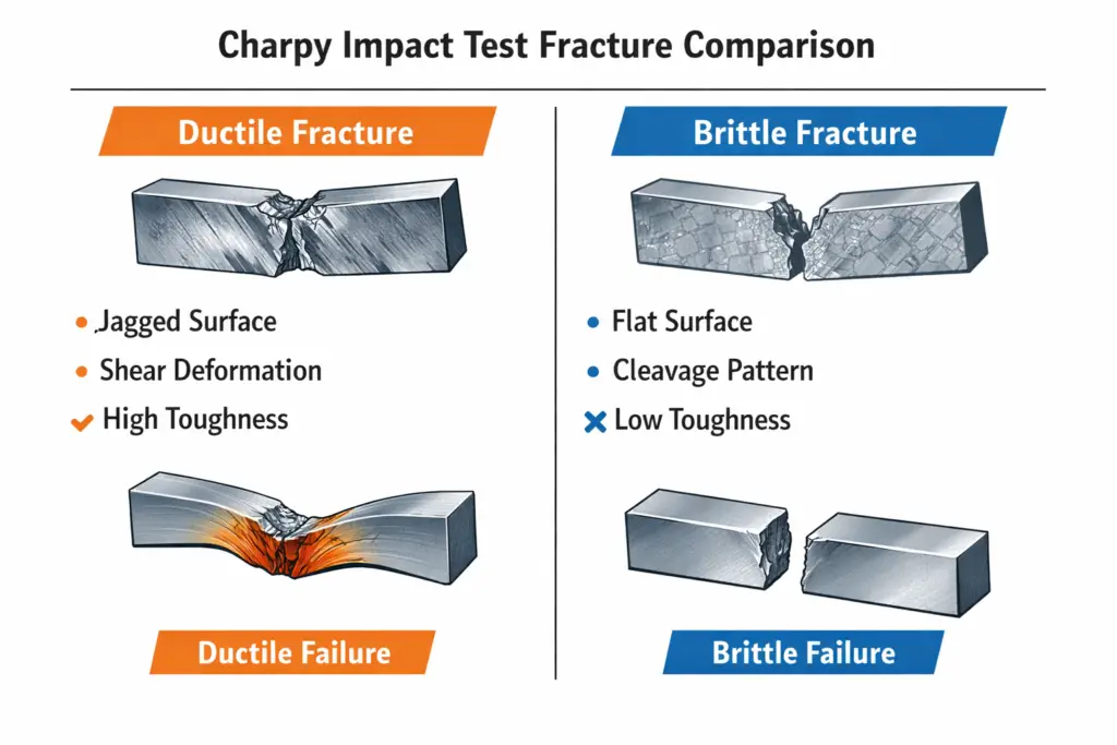
Fracture Surface Analysis
The fracture surface provides qualitative information that complements the energy value:
| Fracture Type | Appearance | Energy Absorbed | Shear Area | Implication |
|---|---|---|---|---|
| Ductile (Shear) | Rough, fibrous, grey-matte | High | > 50% | Good toughness; material deforms before fracturing |
| Brittle (Cleavage) | Flat, faceted, reflective | Low | < 50% | Poor toughness; sudden fracture without warning |
| Mixed | Combination of both zones | Moderate | 20–80% | Transition region — temperature near DBTT |
Percent shear area (also called percent fibrous fracture or percent ductile fracture) is estimated by comparing the relative area of the shear lips and fibrous zones against the total fracture area, typically using a reference chart or image analysis.
Lateral Expansion
Lateral expansion is measured using a micrometer on the compression side of each specimen half, comparing the pre-test width to the post-test width at the point of maximum bulge. It is expressed in millimetres. ASME UG-84 requires a minimum lateral expansion of 0.38 mm (15 mils) for most pressure vessel carbon and low-alloy steels. This criterion is often used alongside the absorbed energy requirement as a secondary acceptance check.
Ductile-to-Brittle Transition Temperature (DBTT)
One of the most important applications of the Charpy test is determining the ductile-to-brittle transition temperature (DBTT) — sometimes called the nil-ductility transition temperature (NDT) or transition temperature — of a metal. This is the temperature range over which a material’s fracture mode shifts from ductile to brittle.
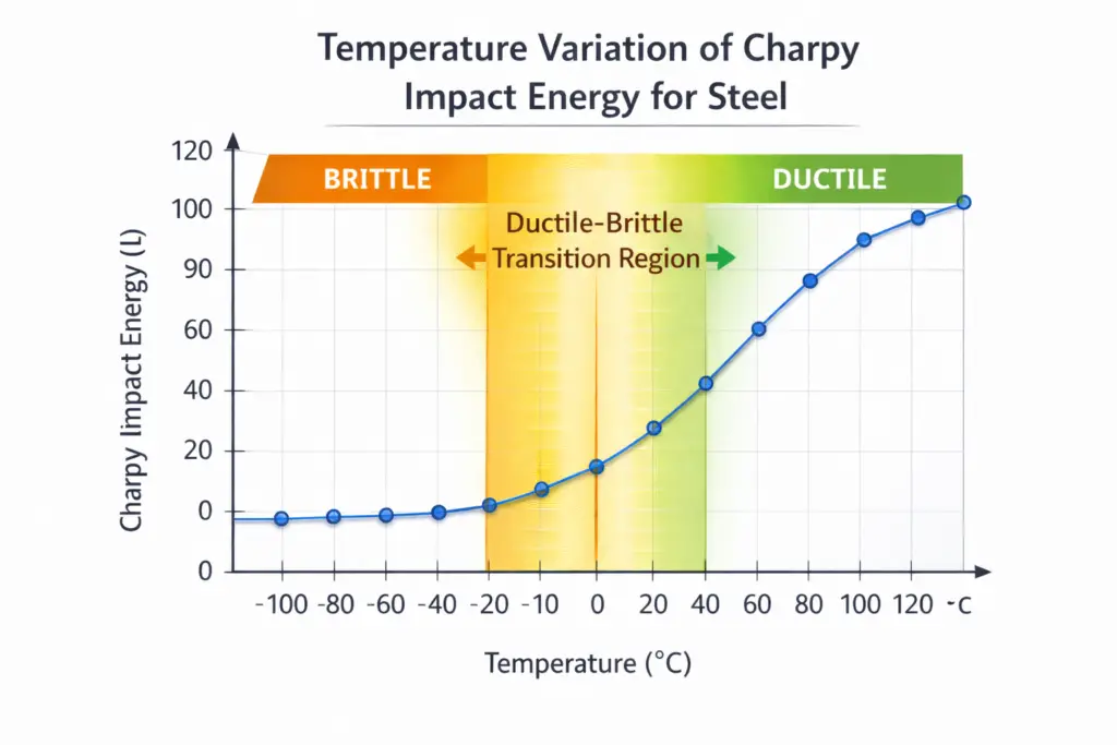
To determine the DBTT, a series of identical Charpy specimens are tested at several temperatures spanning from well above to well below the expected transition range. The results are plotted as absorbed energy (or % shear area) versus temperature, generating the classic S-curve shown above.
Defining the DBTT: Common Criteria
Several criteria are used to define a single temperature value from the S-curve:
- 50% shear area criterion: Temperature at which the fracture surface shows 50% ductile and 50% brittle area — the most commonly cited definition.
- Fixed energy criterion: Temperature at which impact energy reaches a specified value, commonly 27 J (20 ft-lb) for carbon steels, or 40 J for certain code requirements.
- 50% upper-shelf energy: Temperature at which energy is 50% of the maximum (upper-shelf) value.
- ASME MDMT: ASME codes use impact test exemption curves (UCS-66) linked to material thickness and MDMT rather than a single defined DBTT value.
Factors That Affect DBTT
| Factor | Effect on DBTT | Direction |
|---|---|---|
| Carbon content | Increasing C raises DBTT substantially | Increases DBTT |
| Manganese content | Mn lowers DBTT and improves toughness | Lowers DBTT |
| Nickel content | Significant DBTT reduction; key for cryogenic grades | Lowers DBTT |
| Grain size (finer) | Finer grain lowers DBTT (Hall-Petch mechanism) | Lowers DBTT |
| Sulphur / Phosphorus | Tramp elements raise DBTT; embrittlement | Increases DBTT |
| Temper embrittlement (PWHT issue) | Segregation of P, Sb, Sn to grain boundaries raises DBTT | Increases DBTT |
| Strain ageing | Cold work followed by low-temperature ageing raises DBTT | Increases DBTT |
| Normalising / PWHT | Proper heat treatment can lower DBTT significantly | Lowers DBTT |
| Irradiation (nuclear) | Neutron bombardment raises DBTT (embrittlement) | Increases DBTT |
Charpy Impact Testing in ASME Codes
ASME Section VIII Division 1 — UG-84
For pressure vessel fabrication, ASME Section VIII Division 1, paragraph UG-84 is the governing requirement for impact testing. It mandates Charpy testing when a material’s thickness and Minimum Design Metal Temperature (MDMT) combination falls outside the exemption curves defined in Figure UCS-66. The key UG-84 provisions are:
- Test temperature must be at or below the MDMT stamped on the vessel nameplate
- Three specimens are tested; the average must meet the minimum energy requirement
- For carbon and low-alloy steels: minimum average absorbed energy typically 20 J (15 ft-lb) for full-size specimens, with lateral expansion minimum 0.38 mm
- HAZ and weld metal specimens must also be tested when the weld is in the impact-tested zone
- Impact test exemptions (Figure UCS-66) are available based on P-Number group, nominal thickness, and MDMT
- Impact test curve upgrading is possible for PWHT and other conditions (Figure UCS-66.1)
ASME Section IX — Welding Procedure Qualification
When impact testing is a design requirement for a welded joint, ASME Section IX requires that the welding procedure qualification (WPQ) include Charpy impact tests of the weld metal and heat-affected zone (HAZ). Impact test results are recorded on the Procedure Qualification Record (PQR). A change in certain essential variables (base metal P-Number, filler metal classification, heat input, PWHT) requires requalification including re-testing of impact specimens. For further detail, see the ASME Section IX qualification guide and the P-Number and A-Number guide.
Pipeline Codes — API 5L and ASME B31.3
For pipelines and process piping, ASME B31.3 references ASME Section VIII criteria for impact testing of low-temperature services (below −29°C / −20°F for carbon steel). API 5L specifies Charpy minimum absorbed energy requirements for line pipe grades (e.g., X60, X65, X70) based on pipe diameter, wall thickness, and design temperature, with separate requirements for body, weld, and HAZ specimens.
Charpy Test vs. Izod Test — Key Differences
| Feature | Charpy Test | Izod Test |
|---|---|---|
| Specimen orientation | Horizontal, simply supported at both ends | Vertical, clamped at one end (cantilever) |
| Hammer strikes | Opposite face to notch | Same side as notch |
| Standard specimen length | 55 mm | 75 mm |
| Primary application | Metals, weldments, pressure equipment | Plastics, polymers, rubbers |
| Governing standards | ASTM E23, ISO 148-1, ASME, API | ASTM D256, ISO 180 |
| Temperature testing ease | Good — specimen easily conditioned and transferred | More complex clamping at temperature |
| International code usage | Dominant for metals worldwide | Primarily plastics industry |
Applications of Charpy Impact Testing in Industry
Pressure Vessels and Heat Exchangers
Pressure vessels and heat exchangers operating at low temperatures — LPG storage, refrigeration systems, cold separation trains — require impact-tested materials and weld procedures. The Charpy test confirms that the vessel wall can withstand pressure surges or mechanical impacts without brittle fracture initiation. This is mandatory under ASME Section VIII Div.1 (UG-84) and equivalent European codes (EN 13445).
Offshore Structures and Pipelines
Offshore oil and gas structures are exposed to wave slam, dropped object impacts, and North Sea/Arctic temperatures. Impact testing of structural steel (e.g., S355G10+M per EN 10225, or API 2W grades) and weld procedures at temperatures as low as −40°C is a standard project requirement. Sour service environments add an additional dimension, as hydrogen embrittlement can further reduce toughness.
Bridges and Structural Steelwork
Structural steel specifications for bridges (ASTM A709, EN 10025) include impact sub-quality designations (e.g., Grade 50W, or S355J2) where the letter suffix indicates the Charpy test temperature and minimum energy requirements. Design codes mandate appropriate impact sub-quality based on minimum operating temperature and consequence of failure.
Power Generation — Boilers and Turbines
High-temperature creep-resistant steels such as P91 (9Cr-1Mo-V) require carefully controlled PWHT to restore post-weld toughness. Post-PWHT Charpy testing of WPS qualification specimens verifies that the heat treatment cycle has achieved the required toughness alongside the creep properties.
Quality Control in Steel Mills
Steel mills routinely conduct Charpy testing as part of heat-by-heat quality control for impact-tested grades. Results are reported on the Material Test Certificate (MTC), and purchasers verify that the reported values meet the applicable standard’s requirements before accepting the material.
Worked Example: Checking Charpy Acceptance Against ASME UG-84
A carbon steel pressure vessel with SA-516 Grade 70 material is designed for service at −30°C. The nominal shell thickness is 25 mm. Impact testing of the base metal, weld metal, and HAZ is required. Three full-size CVN specimens are tested at −35°C (5°C below the MDMT as required by UG-84). The results are:
Frequently Asked Questions
What is the Charpy impact test and what does it measure?
What are the standard dimensions of a Charpy V-notch specimen?
How is impact energy calculated in the Charpy test?
What is the ductile-to-brittle transition temperature (DBTT)?
What are the ASME UG-84 Charpy impact test requirements?
What is the difference between the Charpy test and the Izod test?
How does temperature affect Charpy impact energy values?
What is lateral expansion in Charpy testing and why does it matter?
Recommended Books on Mechanical Testing and Toughness
Disclosure: WeldFabWorld participates in the Amazon Associates programme (StoreID: neha0fe8-21). If you purchase through these links, we may earn a small commission at no extra cost to you. This helps support free technical content on this site.