Long Range Ultrasonic Testing (LRUT): Complete Guide, Working, Advantages & Applications
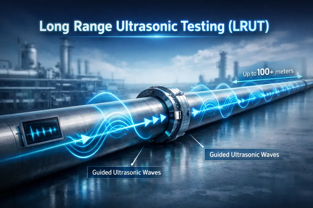
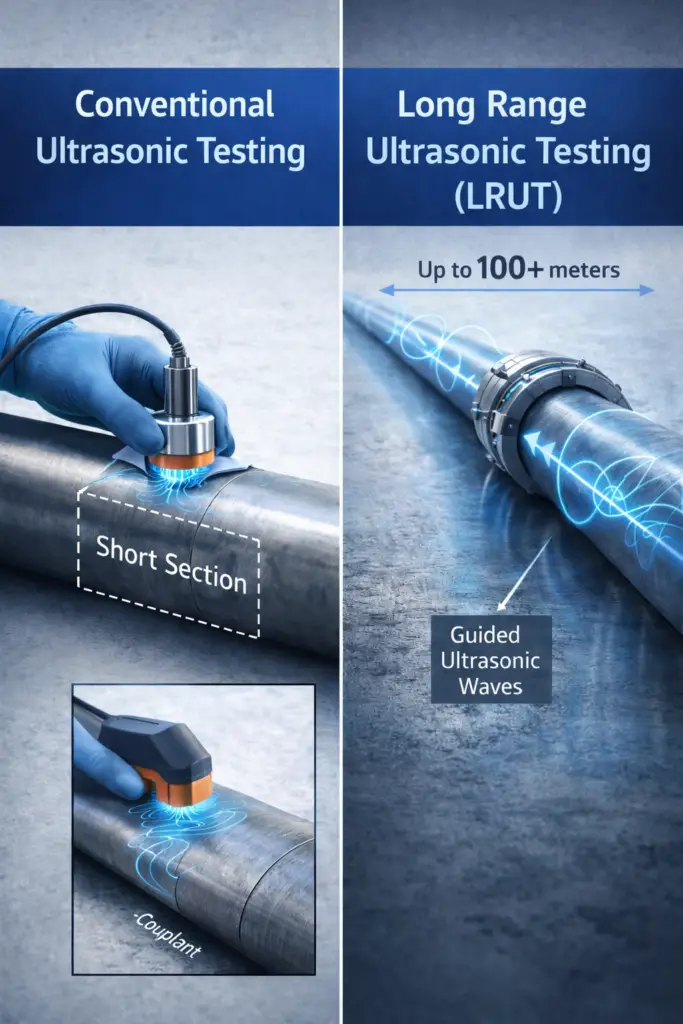
Long Range Ultrasonic Testing (LRUT) — also widely known as Guided Wave Ultrasonic Testing (GWUT) — is one of the most powerful screening tools in modern non-destructive testing (NDT). Unlike conventional pulse-echo ultrasound, which interrogates a small localised volume of material, LRUT propagates guided elastic waves along the entire length of a structure, enabling a single transducer ring to screen 100 metres or more in each direction without moving the instrument. The result is faster, safer, and far less costly pipeline inspection — particularly where insulation, coating, or restricted access would otherwise make conventional methods impractical.
This guide covers the physics of guided wave propagation, how an LRUT system is configured and operated, how signals are interpreted, what defects LRUT can and cannot detect, and where the technique fits in a broader NDT inspection strategy. Whether you are a CWI, CSWIP inspector, corrosion engineer, or plant integrity manager, this article gives you the technical depth needed to understand LRUT and apply it effectively.
What is Long Range Ultrasonic Testing?
LRUT is an NDT technique that excites low-frequency guided ultrasonic waves in a structure and analyses the reflected (and transmitted) signals to locate and characterise changes in the structure’s cross-section. Guided waves differ fundamentally from bulk ultrasonic waves: rather than propagating straight through the wall thickness, guided waves are “guided” by the structure’s geometry — the pipe wall, rail web, or plate thickness — and travel long distances along its axis with relatively low attenuation.
The key enabling characteristic is that guided waves are sensitive to any change in cross-sectional area (CSA). Corrosion, erosion, weld caps, flanges, and supports all alter the local cross-section and therefore produce reflections. By recording the time-of-flight of each reflected echo and knowing the wave velocity for the chosen mode and frequency, the position of every feature along the pipe can be calculated with metre-level accuracy.
Physics of Guided Wave Propagation
Understanding why LRUT works requires a basic grasp of guided wave mechanics. In a hollow cylinder (pipe), multiple guided wave modes can propagate. These modes are solutions to the governing wave equations subject to the free-surface boundary conditions at the inner and outer pipe wall surfaces.
Wave Modes Used in Pipe Inspection
Guided wave modes in pipes are classified using the notation M(n, m), where M is the mode family (L for longitudinal, T for torsional, F for flexural), n is the circumferential order, and m is the branch index.
| Mode | Type | Circumferential Order | Dispersion | Common Use |
|---|---|---|---|---|
| T(0,1) | Torsional | Axisymmetric (n=0) | Non-dispersive | Primary mode — pipe screening |
| L(0,2) | Longitudinal | Axisymmetric (n=0) | Mildly dispersive | High-sensitivity pipe inspection |
| L(0,1) | Longitudinal | Axisymmetric (n=0) | Highly dispersive | Generally avoided |
| F(1,2) | Flexural | Non-axisymmetric | Dispersive | Defect focusing, circumferential location |
The T(0,1) torsional mode is the workhorse of commercial LRUT systems. Its key advantages are: it is non-dispersive (group velocity is constant across the frequency range of interest, so pulses do not spread as they travel), it is purely shear in nature and therefore insensitive to fluid loading inside the pipe (critical for in-service inspection of liquid-filled lines), and it can be excited with good signal-to-noise ratio using piezoelectric or magnetostrictive transducer arrays.
Dispersion and Frequency Selection
Dispersion describes how wave velocity changes with frequency. Highly dispersive modes spread in time as they travel, smearing reflections and reducing defect resolution. The non-dispersive nature of T(0,1) at practical inspection frequencies (15–85 kHz) makes signal interpretation straightforward. Frequency selection is a trade-off:
- Lower frequency (15–30 kHz): Greater range, lower spatial resolution. Suitable for screening very long pipeline sections.
- Higher frequency (50–85 kHz): Better defect resolution and sensitivity to smaller CSA changes, but higher attenuation limits range.
How Does Long Range Ultrasonic Testing Work?
The LRUT inspection process involves four stages: transducer ring deployment, guided wave excitation, signal acquisition, and data analysis. Each stage is described below.
Stage 1 — Transducer Ring Deployment
A collar of piezoelectric or magnetostrictive transducer elements is clamped around the pipe at the chosen test point. The elements are typically arranged in two or three circumferential rows and spaced uniformly around the pipe circumference. This arrangement ensures that the excitation energy is distributed evenly, producing axisymmetric wave modes rather than non-symmetric flexural waves which are harder to interpret.
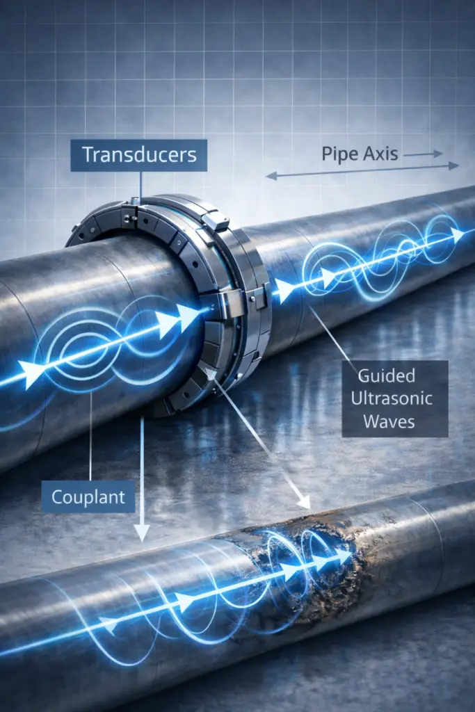
Stage 2 — Guided Wave Excitation
The instrument drives the transducers with a tone-burst signal — typically a Hann-windowed sinusoid of 3 to 10 cycles at the selected centre frequency. The frequency and number of cycles determine the spatial pulse length (and therefore axial resolution) and the mode content of the excitation. Modern instruments allow the operator to select symmetric or antisymmetric phasing of the transducer rows to favour one wave mode family over another.
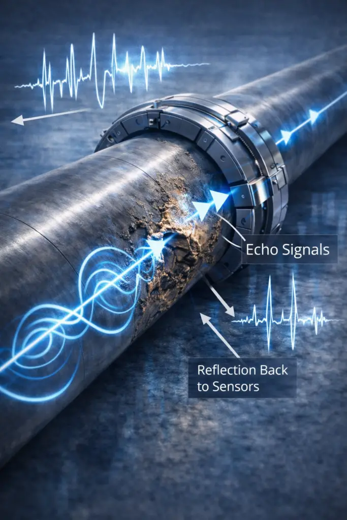
Stage 3 — Signal Acquisition
After excitation, the transducers switch to receive mode. Reflected signals arrive as echoes whose time-of-flight directly corresponds to the distance of the reflecting feature from the ring location (since wave velocity is known). The instrument records and averages multiple transmit-receive cycles to improve signal-to-noise ratio.
Stage 4 — Data Analysis and Signal Interpretation
The acquired time-domain data is typically displayed as an A-scan waveform: amplitude versus distance along the pipe (converted from time-of-flight using the wave velocity). Analysts identify and classify echoes from known features (girth welds, flanges, supports) as reference reflectors, then compare the amplitude of unidentified reflections against these benchmarks to assess likely defect significance.
d = (v × t) / 2
d = distance to reflector (m)
v = group velocity of the selected wave mode (m/s)
t = round-trip time-of-flight (s)
Example — T(0,1) at 40 kHz in steel pipe:
v = 3,230 m/s (independent of frequency for T(0,1))
t = 0.04862 s (echo arrival measured)
d = (3,230 × 0.04862) / 2
d = 78.5 m from the ring location
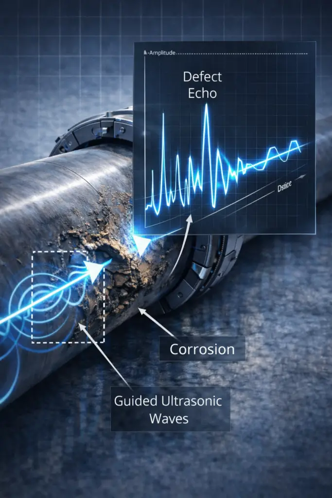
Interpretation of LRUT A-Scan Signals
Signal interpretation is the most skill-intensive aspect of LRUT. All reflections appear on the A-scan as positive (symmetric) or negative (antisymmetric) peaks, but not all peaks indicate defects. A trained analyst must distinguish between structural features, geometric artefacts, and genuine metal loss indications.
Categories of LRUT Signal Features
| Feature Type | Expected Signal Character | Classification |
|---|---|---|
| Girth weld (full penetration) | Moderate amplitude, symmetric, repeating at pipe joint spacing | Known Feature |
| Pipe support / clamp | Moderate to high amplitude; can mask near-side defects | Known Feature |
| Flange / valve | Very high amplitude (near-total reflection); end-of-range marker | Known Feature |
| General corrosion (wall thinning) | Moderate amplitude, may extend over distance; CSA loss calculable | Anomaly — Investigate |
| Localised corrosion pit | Lower amplitude if small; may be below detection threshold | Anomaly — Investigate |
| Coating disbondment | Amplitude change and possible mode conversion | Assess in Context |
| Elbow / bend | High amplitude, mode-converted energy; acts as range limiter | Range Limit |
Cross-Sectional Area Loss Estimation
LRUT systems estimate defect severity as a percentage cross-sectional area (CSA) loss by comparing the reflection amplitude to that from a reference reflector of known CSA change (typically a girth weld). The reflection coefficient R is approximately proportional to the fractional CSA change:
R ≈ ΔA / A
ΔA = change in cross-sectional area at the defect (m²)
A = nominal pipe cross-sectional area of metal (m²)
Detection threshold (industry guideline):
CSA loss ≥ 3–9% is generally detectable depending on frequency and conditions
Below 3% CSA loss: likely below signal-to-noise floor in most field conditions
LRUT vs Conventional Ultrasonic Testing
| Feature | Conventional UT (Pulse-Echo) | LRUT (Guided Wave) |
|---|---|---|
| Inspection range per setup | Centimetres — local area only | Up to 100+ metres each direction |
| Access required | Full surface access along entire length | Single access point for ring placement |
| Insulation removal needed | Yes — complete removal | Minimal — at ring location only |
| Inspection speed | Slow (manual scanning) | Fast (entire section in minutes) |
| Wall thickness measurement | Accurate (0.1 mm) | Not possible |
| Defect depth sizing | Accurate | Not available |
| Buried/insulated pipe | Impractical without excavation | Effective screening |
| CUI detection | Requires insulation removal | Primary application |
| Operating frequency | 1–10 MHz | 15–85 kHz |
| Primary use | Defect sizing and characterisation | Rapid screening and anomaly location |
Defect Detection Capability
LRUT is highly effective for detecting distributed or extended defects that alter the pipe cross-section over an axial length comparable to or greater than the guided wave wavelength. Its capability is more nuanced for localised features.
Readily Detectable Anomalies
- Corrosion under insulation (CUI) — the primary use case; LRUT screens entire runs without insulation removal
- General wall thinning from internal or external corrosion affecting 5% or more CSA
- Erosion damage at bends and reducers causing progressive thinning
- External corrosion at soil-to-air interfaces on buried or partially buried pipelines
- Weld-related anomalies with significant volumetric character (e.g., incomplete fusion causing local cross-section variation)
Difficult or Non-Detectable Anomalies
- Pinhole pits and very localised corrosion occupying less than 3% CSA loss
- Tight planar cracks (very low reflection coefficient for symmetric wave modes)
- Circumferentially oriented cracking (poor wave-crack interaction angle)
- Defects located in or very close to reflective geometric features (elbows, flanges)
Advantages of Long Range Ultrasonic Testing
LRUT offers a compelling combination of technical and operational advantages that make it the preferred first-pass screening tool for large-diameter piping, especially in challenging environments:
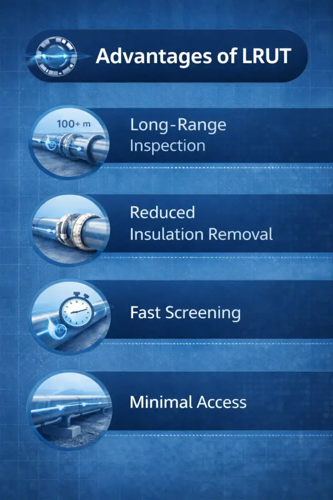
- Long inspection range from one location: Screening 100+ metres per ring placement dramatically reduces the number of access points needed, lowering scaffolding, insulation removal, and excavation costs.
- Minimal insulation removal: Only a small window in the insulation is needed for ring placement. The rest of the insulation system remains intact, avoiding post-inspection re-insulation costs.
- Inspection of inaccessible areas: Buried pipe sections, cased crossings, road crossings, wall penetrations, and elevated sections can all be screened from accessible test points.
- Fast screening: An experienced technician can screen several hundred metres of above-ground piping per day, a rate orders of magnitude faster than conventional UT scanning.
- Non-destructive and safe: LRUT does not require any removal of material or invasive entry into the pipe. Guided waves are low-energy and harmless to personnel and pipe contents.
- In-service inspection: LRUT can be performed on operational pipelines carrying product at process temperatures (within equipment and transducer limits), minimising production downtime.
- Asset integrity programme efficiency: Used within a risk-based inspection (RBI) framework, LRUT enables systematic screening of large inventory, concentrating detailed inspection effort where LRUT confirms anomalies.
Limitations and Constraints of LRUT
No NDT method is universally applicable, and LRUT is no exception. Understanding its constraints is essential for planning an effective inspection strategy.
Technical Limitations
| Limitation | Explanation | Mitigation |
|---|---|---|
| Cannot size defects | Only CSA loss is estimated; depth and exact area unmeasurable | Follow up with contact UT / PAUT |
| Minimum detectable CSA loss ~3–9% | Very small pits fall below signal-to-noise floor | Higher frequency or PAUT for at-risk areas |
| Viscoelastic coating attenuation | Bitumen, polyurethane, rubber coatings absorb wave energy rapidly | Use lower frequency; limit expectations on range |
| Elbows and tees as range limiters | Most wave energy reflects at sharp geometry changes | Position ring between geometry changes; test from both sides |
| Pipe supports mask near-field zones | Supports create high-amplitude signals that can mask local defects | Inspect from both sides of support; apply conventional UT locally |
| Requires specialist interpretation | LRUT A-scans demand PCN/ASNT Level II or III trained analysts | Third-party specialist or certified operator review |
| Liquid-coupled pipe at high temperature | L-mode sensitivity changes with fluid; T-mode preferred | Always specify T(0,1) mode for liquid-filled pipelines |
Industrial Applications of Long Range Ultrasonic Testing
LRUT is deployed across a wide range of industries wherever long, uninterrupted metallic structures require periodic integrity screening.
Oil, Gas, and Petrochemical
The largest user of LRUT. Applications include screening of insulated process pipework for CUI, inspection of above-ground flow lines and transfer pipelines, soil-to-air interface inspection at road crossings, and condition monitoring of jetty pipelines. LRUT integrates naturally with sour service integrity management programmes where external corrosion is a primary degradation mechanism.
Power Generation
Used for steam lines, cooling water headers, and feedwater piping. The ability to inspect elevated and lagged pipework in boiler houses without significant scaffolding makes LRUT economically attractive in power plant outage planning.
Chemical and Process Industries
Process lines carrying corrosive fluids are prime candidates. LRUT identifies sections with elevated corrosion activity, directing resources toward targeted cleaning and re-lining or replacement.
Water and Wastewater Infrastructure
Large-diameter water mains and wastewater pipes can be screened from manholes or access points, detecting wall thinning caused by internal microbially induced corrosion (MIC) or external soil attack.
Railway Track Inspection
Guided waves propagate efficiently along rail webs, enabling rapid screening of rail sections for fatigue cracks and weld defects without track possession.
Structural Members and Tendons
LRUT has been adapted for inspection of tubular structural members in offshore platforms, bridge tendons, and tubular piling where conventional access is impractical.
Integrating LRUT into Risk-Based Inspection (RBI) Programmes
LRUT is most powerful when applied within a structured risk-based inspection (RBI) framework in accordance with API 580 or API 581. In this context, LRUT functions as the primary screening tool for medium- and high-risk lines, with the density of ring placements determined by the assessed corrosion rate, line importance, and consequence of failure.
Typical workflow:
- RBI assessment — identify high-risk segments based on fluid, temperature, operating history, and prior inspection data
- LRUT screening — screen nominated sections, flagging anomalies above the call threshold
- Conventional UT follow-up — apply contact UT, PAUT, or radiography at flagged locations for sizing
- Fitness-for-service assessment — evaluate remaining life based on measured defect size (API 579 / BS 7910)
- Maintenance decision — repair, replace, or monitor with adjusted inspection interval
LRUT Equipment and Transducer Technology
Piezoelectric Systems
Most commercial LRUT systems use piezoelectric transducer arrays. The transducers are arranged in circumferential rows and generate shear horizontal (SH) waves in the pipe wall using dry-coupled wedge elements. Piezoelectric systems offer good frequency flexibility and are suitable for pipes from 50 mm to over 600 mm diameter.
Magnetostrictive Systems
Magnetostrictive (MsS) transduction uses the magnetostrictive effect in ferromagnetic steel. A flexible MsS strip is bonded or clamped to the pipe and driven by a surrounding coil. Magnetostrictive systems excel at generating T(0,1) torsional waves efficiently across a wide frequency range and are often preferred for large-diameter pipes and pipes with irregular surfaces.
Recommended Reading on Ultrasonic Testing and Pipeline Inspection
Disclosure: WeldFabWorld participates in the Amazon Associates programme (StoreID: neha0fe8-21). If you purchase through these links, we may earn a small commission at no extra cost to you. This helps support free technical content on this site.
Frequently Asked Questions about LRUT
What is the inspection range of LRUT?
LRUT can inspect up to 100 metres or more in each direction from a single transducer ring location, giving a total coverage of 200+ metres per test point. The actual range depends on pipe diameter, wall thickness, coating type, operating frequency, and the presence of signal-attenuating features such as elbows, branches, or thick bitumen coatings. In ideal conditions (bare steel, straight run), ranges of 150 metres per direction have been reported with modern systems.
What frequency range is used in LRUT?
LRUT operates at low frequencies, typically between 15 kHz and 85 kHz. Lower frequencies (15–30 kHz) provide longer range but lower resolution, while higher frequencies (50–85 kHz) give better defect resolution at the cost of reduced inspection range. The optimum frequency is selected based on pipe dimensions and target defect size. This contrasts sharply with conventional pulse-echo UT, which operates at 1–10 MHz — roughly 100 times higher.
Can LRUT detect corrosion under insulation (CUI)?
Yes. LRUT is one of the most effective screening tools for corrosion under insulation (CUI) because guided waves travel along the pipe wall beneath the insulation without requiring its removal. Only a small window is needed at the transducer ring location. When LRUT flags a suspect area, targeted insulation removal and conventional UT or PAUT can be applied for sizing. This makes LRUT ideal for CUI inspection programmes on process pipework in oil and gas and petrochemical plants.
What wave modes are used in guided wave testing?
The two primary wave modes used in LRUT are torsional (T-mode) and longitudinal (L-mode) guided waves. Torsional waves, specifically T(0,1), are the most widely used in pipe inspection because they are non-dispersive at low frequencies, have a relatively flat group velocity, and are insensitive to pipe contents — making them suitable for liquid-filled and gas-filled lines alike. Longitudinal waves (L(0,2)) offer faster propagation but are sensitive to fluid loading inside the pipe and require more careful interpretation, particularly for liquid-filled systems.
Is LRUT a replacement for conventional ultrasonic testing?
No. LRUT is a screening technique, not a sizing tool. It identifies the location of potential defects but cannot measure defect depth or precise geometry accurately enough to meet fitness-for-service assessment requirements under API 579 or BS 7910. Any anomaly flagged by LRUT must be followed up with conventional UT, phased array UT (PAUT), or other appropriate NDT methods for detailed characterisation and sizing before maintenance decisions are made. See our mechanical testing guide for an overview of complementary techniques.
What is the minimum detectable defect size for LRUT?
LRUT detects changes in cross-sectional area rather than discrete defect dimensions. The general detection threshold is approximately 3 to 9 percent cross-sectional area loss (CSA loss), depending on operating frequency, pipe size, coating condition, and signal-to-noise ratio. This means LRUT is well-suited for detecting general wall thinning and widespread corrosion but may miss very small localised pits below the detection threshold. Detection sensitivity improves with higher operating frequency but at the cost of reduced inspection range.
Which industries use Long Range Ultrasonic Testing?
LRUT is used extensively in oil and gas pipelines (onshore and offshore), petrochemical and refinery piping, power plant steam and water lines, chemical plant process pipework, railway track inspection, and structural member inspection. It is especially valuable for buried or elevated pipelines, cased pipe crossings, and insulated process lines where conventional scanning is impractical. Integration with API 580 risk-based inspection programmes is standard practice in oil and gas facilities.
What are the main limitations of LRUT?
Key limitations include: inability to accurately size defects, reduced sensitivity to short axial or circumferentially oriented defects, signal attenuation from viscoelastic coatings (e.g., bitumen and polyurethane), complex geometry features such as bends, tees, and reducers causing signal scattering, and the requirement for highly trained analysts to interpret A-scan data reliably. Pipe contents and temperature also influence propagation behaviour. These constraints mean LRUT is always combined with quantitative NDT methods when anomalies are confirmed. Using LRUT alongside systematic welding and inspection protocols maximises asset integrity outcomes.
Conclusion
Long Range Ultrasonic Testing is a technically sophisticated and operationally powerful NDT screening method that has transformed pipeline integrity management across multiple industries. By harnessing the physics of guided wave propagation — particularly the non-dispersive T(0,1) torsional mode — LRUT allows inspection teams to screen hundreds of metres of piping from a single access point, without full insulation removal and without taking lines out of service.
Its core strength is speed and coverage: no other NDT method can screen comparable lengths of pipe per mobilisation. Its inherent limitation — the inability to size defects — means it always works as the first stage of a two-stage inspection strategy, with conventional UT, PAUT, or radiography providing the quantitative data needed for engineering decisions. When properly applied within an RBI framework, LRUT is an indispensable tool for cost-effective, risk-driven asset integrity management.
For related inspection and testing topics, explore our guides on CTOD testing methodology, Charpy impact testing, welding inspection checklists, and the fundamentals of corrosion types and mechanisms.