Half Wave vs Full Wave Rectifier: Working Principle, Efficiency & Welding Applications
The half wave vs full wave rectifier comparison is one of the foundational concepts in electrical engineering and is directly relevant to how welding power sources convert mains AC supply into the stable DC current required for arc welding. A rectifier is an electronic circuit that exploits the one-directional conduction property of semiconductor diodes to change alternating current (AC) into direct current (DC). Understanding how each rectifier type operates — and where each is used — is essential knowledge for welding engineers, CWI inspectors evaluating power source suitability, and fabrication professionals troubleshooting arc instability.
In welding, the quality of DC output from a rectifier has a direct impact on arc stability, spatter levels, bead geometry, and ultimately weld quality. A poorly rectified supply — high ripple, discontinuous current — will produce an unstable arc regardless of how well the welder sets parameters. This guide covers both rectifier types from first principles: diode behaviour, circuit configuration, mathematical output analysis, ripple factor, efficiency, and practical applications in SMAW, GMAW, and GTAW power sources.

What Is a Rectifier?
A rectifier is an electrical circuit that converts bidirectional alternating current (AC) into unidirectional direct current (DC). It does this by exploiting the one-way conduction property of semiconductor diodes. A diode is a two-terminal semiconductor device (P-N junction) that permits current flow when forward-biased (anode positive relative to cathode) and blocks current when reverse-biased (anode negative relative to cathode).
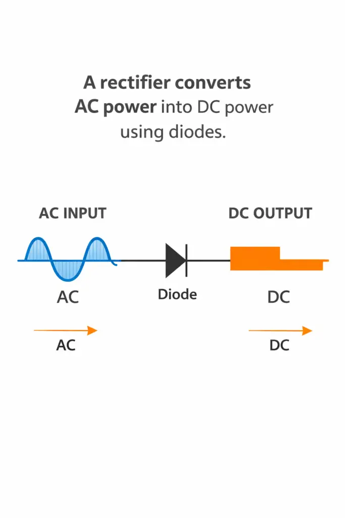
The Diode as a Switching Element
When AC voltage is applied to a rectifier circuit, the diode alternately conducts and blocks current in synchrony with the AC waveform:
- During the positive half cycle: The anode is at a higher potential than the cathode — the diode is forward biased and conducts current freely.
- During the negative half cycle: The cathode is at a higher potential — the diode is reverse biased and blocks current flow (except for a negligibly small leakage current).
This selective conduction is the mechanism that converts bidirectional AC into unidirectional DC. The key difference between rectifier types lies in how many diodes are used and how much of the AC waveform is recovered as DC output.
Half Wave Rectifier: Circuit, Working & Characteristics
A half wave rectifier is the simplest rectifier configuration, consisting of a single diode placed in series with the AC supply and the load. It converts only one half of the AC cycle — either positive or negative — into DC output, and completely blocks the other half.
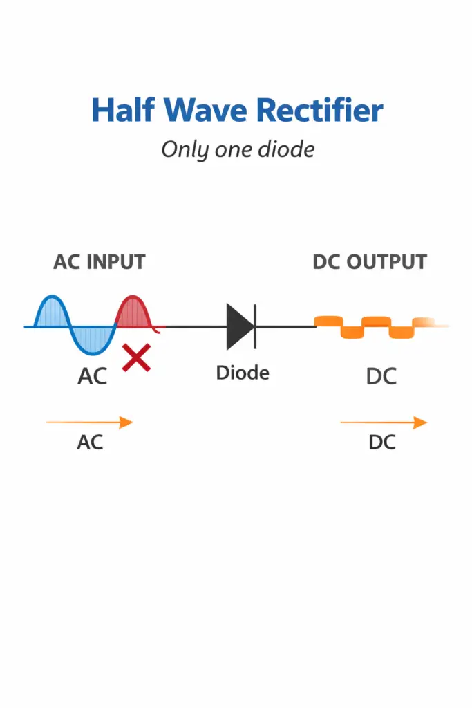
Working Principle
The AC source supplies a sinusoidal voltage: v(t) = Vm sin(ωt), where Vm is the peak voltage and ω is the angular frequency.
- Positive half cycle (0 to π): The diode is forward biased. Current flows through the load resistance RL. The output voltage equals the input minus the diode forward drop: vout = Vm sin(ωt) − Vf.
- Negative half cycle (π to 2π): The diode is reverse biased. No current flows. Output voltage is zero.
Mathematical Output Analysis
Characteristics and Limitations
The half wave rectifier’s key disadvantage is that it uses only half of the available AC waveform, resulting in a low average output voltage (only 31.8% of peak voltage) and extremely high ripple. The output contains a fundamental frequency component equal to the supply frequency (50 Hz in India/EU, 60 Hz in North America), making filtering difficult and expensive.
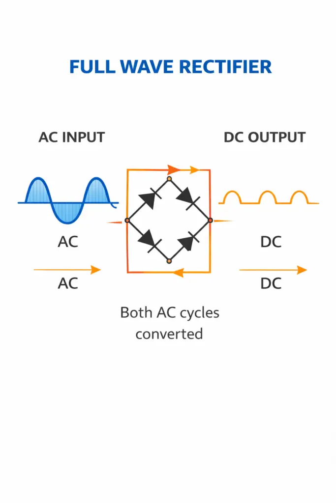
Full Wave Rectifier: Circuit Configurations & Working
A full wave rectifier converts both half cycles of the AC input into DC output. It does this by inverting the negative half cycle so that both positive and negative portions of the sine wave contribute to a unidirectional output current. Two circuit topologies achieve full wave rectification.
Centre-Tapped Full Wave Rectifier
This configuration uses two diodes and a centre-tapped transformer. The centre tap provides a common reference (ground), while each half of the transformer secondary drives one diode alternately.
- During the positive half cycle, Diode 1 conducts; Diode 2 is reverse biased.
- During the negative half cycle, Diode 2 conducts; Diode 1 is reverse biased.
- Both diodes deliver current through the load in the same direction, producing continuous DC output.
Bridge Rectifier (Four-Diode Full Wave)
The bridge rectifier is the most commonly used configuration. Four diodes are arranged in a bridge (H-bridge) pattern. No centre-tapped transformer is needed, making it more economical for high-voltage applications.
- Positive half cycle: Diodes D1 and D3 conduct; D2 and D4 are reverse biased. Current flows through load from top to bottom.
- Negative half cycle: Diodes D2 and D4 conduct; D1 and D3 are reverse biased. Current still flows through load from top to bottom (same direction).
Note that the effective output voltage of a bridge rectifier is reduced by two diode forward voltage drops (2 × 0.7 V = 1.4 V) since two diodes are always in series with the current path. This is a negligible loss at the high voltages used in most industrial applications.
Mathematical Output Analysis
Half Wave vs Full Wave Rectifier — Detailed Comparison
| Parameter | Half Wave Rectifier | Full Wave Rectifier |
|---|---|---|
| Number of diodes | 1 | 2 (centre-tap) or 4 (bridge) |
| AC cycles utilised | One half only | Both halves |
| Average DC output (Vavg) | 0.318 × Vm | 0.637 × Vm |
| RMS output voltage | 0.5 × Vm | 0.707 × Vm |
| Ripple factor (γ) | 1.21 (High) | 0.48 (Low) |
| Ripple frequency | f (same as supply) | 2f (twice the supply frequency) |
| Efficiency | 40.6% | 81.2% |
| Form factor | 1.57 | 1.11 |
| Peak Inverse Voltage (PIV) | Vm | Vm (bridge) / 2Vm (centre-tap) |
| Transformer utilisation factor (TUF) | 0.287 | 0.812 (bridge) |
| DC saturation in transformer | Yes — serious problem | No — symmetric operation |
| Cost / complexity | Very low (1 diode) | Moderate (2–4 diodes + filter) |
| Practical applications | Rare (teaching only) | Widely used |
| Welding suitability | Not suitable | Standard for all DC welding |
Three-Phase Bridge Rectifier in Welding Power Sources
Industrial welding equipment rated above approximately 200 A almost invariably uses a three-phase bridge rectifier rather than a single-phase design. Drawing power from all three phases of a three-phase supply and using six diodes (two per phase), three-phase rectification produces an output that barely dips between peaks — the ripple is nearly eliminated without any filter capacitor.
For SMAW welding with cellulosic or low-hydrogen electrodes, and for precision GTAW/TIG welding, the near-pure DC from a three-phase bridge rectifier provides the arc stability necessary for consistent penetration and fusion quality. Even small variations in arc current can cause incomplete fusion or excess reinforcement when welding root passes on pressure vessel joints to ASME Section IX requirements.
Rectifier Types in Welding Power Sources
Understanding rectifier types is directly relevant to understanding polarity in welding — DCEP (Direct Current Electrode Positive) and DCEN (Direct Current Electrode Negative) are only available when the welding machine output is stable DC. The quality of that DC depends entirely on the rectifier circuit.
SMAW (Stick) Welding Rectifiers
Early SMAW machines were AC transformer-based. Modern DC rectifier sets replaced these because DC arc is more stable, especially for low-hydrogen E7018 and similar electrodes. A three-phase bridge rectifier with a smoothing inductor (choke) in series with the output produces the flat, stable DC required. The inductor stores energy in its magnetic field during current troughs, releasing it to fill the gaps and further smooth the ripple.
MIG/GMAW Rectifiers
For MIG/GMAW welding, the DC output must be particularly stable because the wire feed and arc length are tightly linked — any current ripple disturbs the metal transfer and can cause erratic wire burn-back or stubbing. Modern inverter-based GMAW machines convert mains AC to high-frequency AC (20–100 kHz) using transistors, then rectify this high-frequency output. The high frequency makes filtering trivial — even a small capacitor effectively eliminates ripple at 100 kHz.
TIG/GTAW Rectifiers
Precision TIG welding of thin-gauge stainless steel or titanium on pressure vessel fabrication work requires extremely stable DC. A variation of even 2–3 A in arc current can cause dimensional variation in penetration bead width on critical root passes. Three-phase bridge rectifiers with high-value smoothing capacitors — or modern inverter rectifiers — provide the near-ideal DC required. Use the TIG settings calculator to determine optimal parameters for your material and position.
| Welding Process | Current Type | Rectifier Used | Ripple Requirement |
|---|---|---|---|
| SMAW (low-hydrogen) | DCEP | 3-phase bridge + choke | < 10% |
| SMAW (cellulosic) | DCEP | 3-phase bridge | < 10% |
| GMAW (MIG) | DCEP | Inverter rectifier | < 5% |
| GTAW (TIG) — steel/SS | DCEN | Inverter rectifier | < 3% |
| GTAW — aluminium | AC (HF) | No rectification | N/A |
| SAW | DC or AC | 3-phase bridge (DC mode) | < 10% |
| Half wave (hypothetical) | DC (pulsating) | Single diode | 121% — unusable |
Smoothing and Filtering Rectifier Output
Raw rectifier output — even from a full wave bridge — contains significant AC ripple superimposed on the DC level. In most applications, this ripple must be reduced by adding smoothing components after the rectifier stage.
Capacitor Filter
A large electrolytic capacitor connected across the load charges to the peak voltage during each half cycle and discharges slowly into the load between peaks. The larger the capacitance and the higher the load impedance (lower load current), the better the smoothing. For a full wave rectifier with capacitor filter:
Inductor (Choke) Filter
In high-current welding power sources, an inductor (choke) in series with the output is preferred over capacitors. The inductor opposes rapid changes in current — it stores energy during current peaks and releases it during troughs, smoothing the output current waveform. A choke with adequate inductance also improves GMAW arc stability during metal transfer transitions.
Modern Inverter Welding Machines: Beyond Simple Rectifiers
Contemporary inverter-based welding power sources take rectification to a new level. They use a two-stage process:
- First rectifier stage: Mains AC (50/60 Hz) is rectified by a full wave bridge rectifier to produce raw DC. No elaborate filtering is needed at this stage.
- Inverter stage: The raw DC is switched on and off at very high frequency (typically 20–100 kHz) by IGBTs (Insulated Gate Bipolar Transistors) or MOSFETs, generating high-frequency AC.
- High-frequency transformer: A small, lightweight transformer steps the high-frequency AC to the required welding voltage. Because the frequency is so high, the transformer can be 50–100 times smaller and lighter than a mains-frequency unit of the same power rating.
- Second rectifier stage: The transformer secondary output is rectified again (usually by fast-recovery diodes or synchronous rectifiers) to produce clean DC for the welding arc.
This architecture explains why modern inverter welding machines are so compact and lightweight compared to older transformer-rectifier designs. The high switching frequency makes ripple filtering trivially easy, and the output DC is essentially pure — far better than any simple half-wave or full-wave rectifier operating at 50 Hz could achieve.
Applications and Which Rectifier Is Better
In almost every real engineering and fabrication application, the full wave rectifier — or its modern evolution in inverter technology — is the unambiguous choice. Here is a clear breakdown by use case:
| Application | Best Rectifier | Reason |
|---|---|---|
| Industrial DC welding power source | 3-phase bridge | Lowest ripple, highest efficiency, stable arc |
| Battery charger | Full wave bridge | Smooth DC reduces charge ripple and battery heating |
| DC motor drive | Full wave bridge | Reduces torque ripple, smoother motor operation |
| Power supply unit (PSU) | Full wave bridge + filter | Stable regulated DC output required |
| Signal demodulation | Half wave (envelope detection) | Simplicity needed; peak detection, not smooth DC |
| Teaching / demonstration circuits | Half wave | Shows rectification principle clearly; minimal components |
| Low-power indicator circuits | Half wave | Load current is low; ripple effect is minor |
Recommended Reading: Electrical Engineering & Welding Power Sources
Electronics: Principles & Applications
Comprehensive coverage of diodes, rectifiers, power supplies, and semiconductor devices for engineering students.
View on AmazonWelding Power Sources & Arc Physics
In-depth reference on welding machine design, rectifier circuits, inverter technology, and arc characteristics.
View on AmazonPower Electronics by P.S. Bimbhra
Standard Indian engineering reference for rectifiers, thyristors, inverters, and controlled power conversion circuits.
View on AmazonIndustrial Welding Handbook
Practical guide to welding equipment, power source selection, process parameters, and electrical troubleshooting for fabricators.
View on AmazonDisclosure: WeldFabWorld participates in the Amazon Associates programme (StoreID: neha0fe8-21). If you purchase through these links, we may earn a small commission at no extra cost to you. This helps support free technical content on this site.
Frequently Asked Questions
What is the main difference between a half wave and a full wave rectifier?
A half wave rectifier uses a single diode and converts only one half (either positive or negative) of the AC cycle into DC, leaving the other half blocked. A full wave rectifier converts both halves of the AC cycle into unidirectional DC, either using two diodes with a centre-tapped transformer or four diodes in a bridge configuration.
Full wave rectification is far more efficient — approximately 81.2% vs 40.6% — and produces smoother DC output with a ripple factor of 0.48 compared to 1.21. In SMAW welding and other arc welding processes, only full wave or three-phase bridge rectification is used in practice.
Why is the full wave rectifier more efficient than the half wave?
Full wave rectifiers achieve approximately 81.2% theoretical efficiency compared to 40.6% for half wave rectifiers. This difference occurs because the full wave circuit utilises the entire AC waveform — both positive and negative half cycles contribute to the DC output — whereas the half wave circuit discards one full half cycle, wasting half the available input power.
Additionally, the half wave design causes DC magnetisation of the transformer core (because current flows in only one direction through the secondary winding), increasing core losses and reducing transformer utilisation factor to a mere 0.287 versus 0.812 for the bridge configuration.
What is ripple factor and why does it matter in welding?
Ripple factor is the ratio of the RMS value of the AC component superimposed on the DC output to the average DC output value. It is calculated as: γ = VAC(rms) / VDC(avg). A lower ripple factor means smoother, more stable DC output. A value of zero would represent perfect DC; a value of 1.21 (half wave) means the AC ripple amplitude is larger than the DC average — essentially a very poor DC supply.
In welding, high ripple causes arc instability, increased spatter, inconsistent bead geometry, and difficulty maintaining a stable arc length. Full wave rectifiers have a ripple factor of approximately 0.48 compared to 1.21 for half wave, making them the standard choice in all practical welding power sources. To learn more about how polarity and current affect the arc, see the guide on polarity in welding.
What type of rectifier is used in welding machines?
Modern welding machines predominantly use full wave bridge rectifiers. Industrial machines rated above 200 A typically use three-phase bridge rectifiers (six diodes) because they reduce ripple to approximately 4% without extensive filtering — far smoother than a single-phase full wave design at 48% ripple.
The latest generation of inverter welding machines uses a two-stage approach: a full wave bridge rectifies the mains supply, then an inverter converts this to high-frequency AC which is transformed and rectified again. This approach achieves near-perfect DC output and allows the machine to be compact, lightweight, and highly efficient. Learn more about process-specific settings with the MIG settings calculator and TIG settings calculator.
What is the peak inverse voltage (PIV) for each rectifier type?
For a half wave rectifier, the peak inverse voltage across the diode equals Vm (the peak input voltage). For a full wave bridge rectifier, each diode must withstand a PIV of Vm — the same as the half wave case. However, for a centre-tapped full wave rectifier, the PIV is 2Vm per diode, because each diode sees the full secondary voltage when the other diode conducts.
This means bridge rectifiers can use the same diode voltage rating as a half wave design for the same output voltage, making them more economical than centre-tapped designs at high voltages. In welding equipment, the rectifier diodes are typically rated to handle many times the normal PIV to provide a safety margin against voltage transients from load switching.
How does a three-phase bridge rectifier differ from a single-phase full wave rectifier?
A three-phase bridge rectifier uses six diodes (two per phase) and draws power from all three phases simultaneously. Its output ripple frequency is six times the supply frequency (300 Hz for a 50 Hz supply), compared to twice the supply frequency (100 Hz) for a single-phase full wave rectifier. This makes three-phase rectification far smoother — ripple factor drops to approximately 0.04 (4%) compared to 0.48 (48%) for single-phase full wave.
Three-phase rectifiers also provide better power balance across the supply phases, higher efficiency (near 99%), and require no large filter components because the output waveform barely dips between peaks. They are the standard for all high-current industrial welding power sources used for Submerged Arc Welding (SAW) and heavy SMAW applications.
What is form factor and how is it related to ripple factor?
Form factor (FF) is the ratio of the RMS output voltage to the average (DC) output voltage: FF = Vrms / Vavg. For a half wave rectifier, FF = π/2 ≈ 1.57. For a full wave rectifier, FF = π/(2√2) ≈ 1.11. A form factor of 1.0 would represent perfect DC with no ripple.
The relationship between form factor and ripple factor is: γ = √(FF² − 1). This means you can calculate ripple factor directly from form factor. For the half wave case: γ = √(1.57² − 1) = √(2.465 − 1) = √1.465 ≈ 1.21. For full wave: γ = √(1.11² − 1) = √(1.232 − 1) = √0.232 ≈ 0.48. These values confirm the full wave design as the overwhelming choice for any DC power application.
Can I use a half wave rectifier for DC welding?
Technically, a half wave rectifier produces DC (current flows in one direction only), but its output is so poor — ripple factor 1.21, efficiency 40.6%, discontinuous current with large gaps — that it is completely unsuitable for arc welding in any professional or code-quality context. The pulsating, discontinuous DC would cause severe arc instability, excessive spatter, and inconsistent penetration.
Furthermore, using a half wave rectifier as a welding power source would saturate the transformer core with DC magnetisation, causing overheating and premature transformer failure. All code-compliant welding — whether to ASME Section IX or AWS D1.1 — requires stable, consistent DC output that only full wave (or three-phase) rectification can provide.
Conclusion
The comparison of half wave vs full wave rectifiers reveals a clear engineering verdict: the half wave rectifier, while simple and instructive as a teaching circuit, has almost no role in practical electrical or fabrication engineering. Its 40.6% efficiency, 1.21 ripple factor, transformer core saturation problem, and discontinuous output make it unsuitable for any load that requires stable, smooth DC.
The full wave bridge rectifier is the workhorse of DC power conversion — used in every welding power source, battery charger, motor drive, and regulated power supply. For welding applications specifically, the three-phase bridge rectifier and modern inverter rectifier architectures take this further, achieving near-perfect DC output that enables stable arcs, consistent penetration, and weld quality that meets the most stringent code requirements. Understanding these fundamentals equips the welding engineer and CWI inspector to diagnose arc instability problems, evaluate power source suitability, and make informed equipment selection decisions on the shop floor and in the field.