Hydrotest Pressure Calculator: ASME B31.3 and Section VIII Div. 1
Last updated:
Quick Answer: Hydrotest pressure is the design pressure multiplied by a code-specified test factor and, where allowable stress values differ, by the ratio of allowable stress at test temperature to allowable stress at design temperature. ASME B31.3 process piping uses 1.5 times design pressure; ASME Section VIII Division 1 vessels use 1.3 times MAWP (UG-99). Pneumatic tests use a lower factor of 1.1 times.
Before a new or repaired pressure system enters service, it must prove it can hold pressure without leaking or yielding. The hydrotest pressure calculator logic on this page derives that proof pressure directly from ASME B31.3 (Process Piping) and ASME BPVC Section VIII Division 1 (Pressure Vessels), the two codes most commonly referenced on oil and gas, power, and process plant projects. Getting the test pressure wrong in either direction creates a real problem: too low and the test does not demonstrate the required margin; too high and there is a risk of yielding the material or overloading gaskets, supports, and test blinds.
This guide walks through the governing formulas, the allowable stress ratio that most engineers forget to apply, the difference between hydrostatic and pneumatic test factors, and a fully worked example for both a piping system and a pressure vessel. Use the calculator below to get an instant test pressure, then read the sections that follow to understand exactly where each number comes from.
- ASME B31.3 hydrostatic test pressure is 1.5 times the design pressure, adjusted by the allowable stress ratio at test and design temperature.
- ASME Section VIII Division 1 hydrostatic test pressure (UG-99) is 1.3 times the maximum allowable working pressure (MAWP), similarly adjusted by the stress ratio.
- Pneumatic testing uses a lower multiplier, typically 1.1 times, because compressed gas stores far more dangerous energy than water.
- The stress ratio is capped by the applicable code edition; it is never taken as a value that would push the test stress above a safe fraction of yield strength.
- Hydrostatic testing with water is the default method; pneumatic testing is reserved for systems that cannot tolerate moisture or cannot be filled with liquid.
What Is Hydrotest Pressure?
Hydrotest pressure is the elevated internal pressure, above normal operating pressure, that a piping system or pressure vessel is subjected to in order to verify structural integrity before service. The test is run once fabrication, welding, and non-destructive examination are complete, and it is usually the last mechanical checkpoint before a system is handed over for commissioning.
The test pressure is never the same as the design pressure. Codes apply a multiplier, sometimes called the test factor, so the system is proven at a margin above its rated condition. That margin exists because normal operation includes safety factors already, but a one-time overpressure test at a higher level catches flaws that a test at design pressure would miss: undersized welds, porosity, incomplete penetration, or a mis-torqued flange.
Governing codes: ASME B31.3 covers process piping in refineries, chemical plants, and terminals. ASME BPVC Section VIII Division 1 covers unfired pressure vessels such as drums, columns, and heat exchangers. ASME B31.1 (power piping) and ASME B31.4/B31.8 (pipelines) use related but distinct test factors, noted in the quick reference table below.
Hydrotest Pressure Calculator
Select the governing code, enter the design pressure or MAWP, and enter the allowable stress values if the test temperature differs from the design temperature. Leave the stress fields blank to use a stress ratio of 1.0.
Calculate Hydrotest Pressure
How Is ASME B31.3 Hydrotest Pressure Calculated?
ASME B31.3 requires that process piping be leak tested after fabrication, with a hydrostatic test as the default method. The hydrostatic test pressure at any point in the system is derived from the design pressure of that piping section.
The stress ratio term exists because a piping system designed for an elevated operating temperature has a lower allowable stress than the same material has at ambient test temperature. Testing it cold, at 1.5 times design pressure alone, would under-stress the joint relative to what the code intends. The ratio corrects for that by raising the test pressure proportionally. The code also limits how large this ratio may be taken, so that the resulting test pressure does not approach the material’s yield strength; consult the allowable stress tables and the governing paragraph of the edition in force on your project for that limit.
Caution: Test pressure is a piping-section property, not a single plant-wide number. A system with multiple design pressures (for example, different branches protected by different relief devices) may require sectional testing or a single test at the highest governing design pressure, with lower-rated components temporarily isolated or blinded.
How Is Section VIII Div. 1 Hydrotest Pressure Calculated (UG-99)?
ASME BPVC Section VIII Division 1, paragraph UG-99, sets the minimum hydrostatic test pressure for a pressure vessel at 1.3 times the maximum allowable working pressure (MAWP), corrected by the ratio of allowable stress at test temperature to allowable stress at design temperature.
The same logic applies as in B31.3: a vessel rated for an elevated design temperature has a reduced allowable stress at that temperature, so the ambient-temperature hydrotest pressure is increased to compensate. For most carbon steel vessels tested at ambient shop or site temperature, the ratio is close to 1.0 unless the design temperature is significantly elevated or the vessel uses a material whose allowable stress changes sharply with temperature.
| Code | Application | Governing Clause | Hydrostatic Factor |
|---|---|---|---|
| ASME B31.3 | Process piping | Chapter VI, Testing | 1.5 × P |
| ASME B31.1 | Power piping | Chapter VI, Testing | 1.5 × P |
| ASME Section VIII Div. 1 | Pressure vessels | UG-99 | 1.3 × MAWP |
Hydrostatic vs. Pneumatic Test Pressure
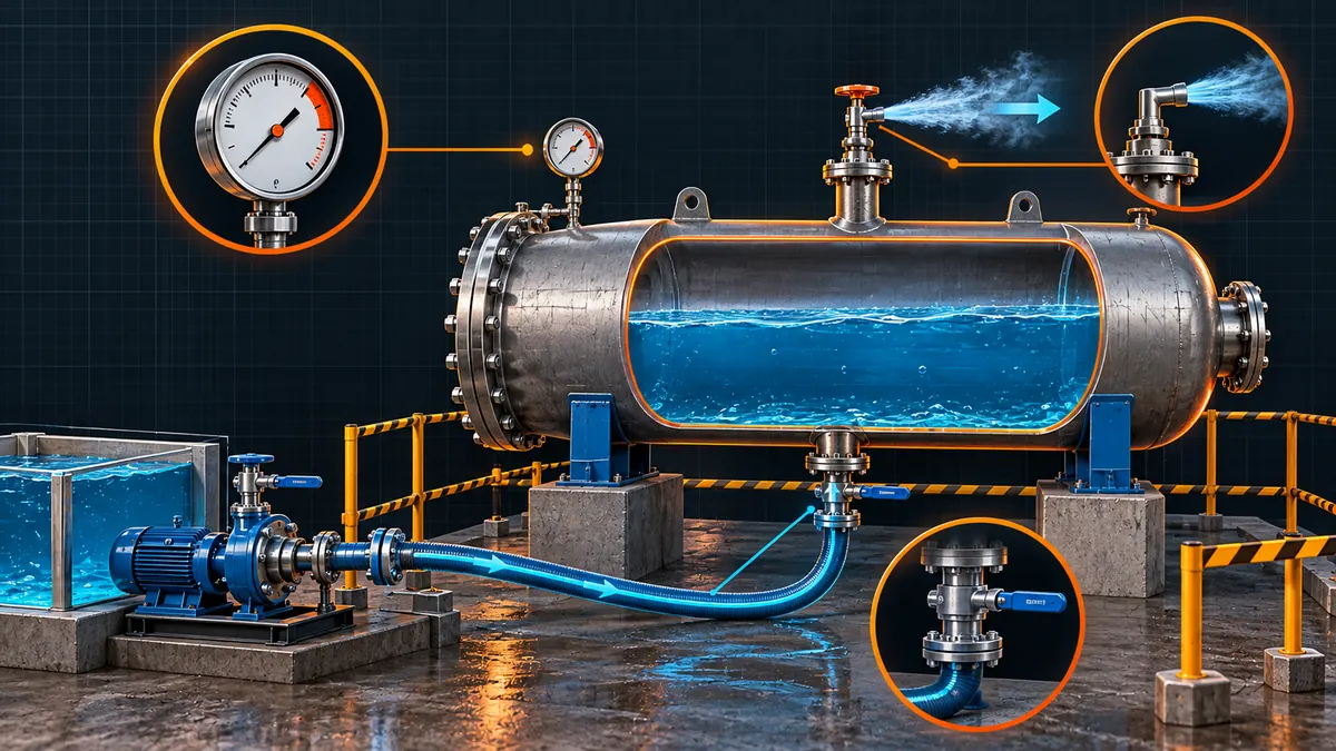
Hydrostatic testing with water is the default method under both codes because water is nearly incompressible: if a joint fails during the test, the stored energy release is small and localized. Pneumatic testing with air or an inert gas stores far more energy at the same pressure, so both codes reduce the pneumatic test factor and add procedural precautions such as a slow, staged pressurization and personnel exclusion zones.
| Aspect | Hydrostatic | Pneumatic |
|---|---|---|
| Typical test medium | Water, often with a corrosion inhibitor | Air, nitrogen, or another inert gas |
| B31.3 factor | 1.5 × P | 1.1 × P |
| Section VIII Div. 1 factor | 1.3 × MAWP (UG-99) | 1.1 × MAWP (UG-100) |
| Stored energy at failure | Low Preferred | High Extra precautions |
| Typical use case | Default for most piping and vessels | Systems that cannot be filled with liquid or dried afterward |
Where is pneumatic testing actually used? Dry gas systems, systems with internals sensitive to moisture, systems where the structure cannot support the weight of water, or locations where water disposal or freezing is a problem are the usual drivers. Because of the higher stored-energy risk, project specifications frequently require additional management-of-change approval before a pneumatic test replaces a hydrostatic one.
Worked Example
Consider a carbon steel process piping system designed for 20 bar(g) at 200°C, to be hydrostatically tested at ambient shop temperature. From the applicable allowable stress table: Sd (at 200°C) = 118 MPa, St (at ambient test temperature) = 138 MPa.
Now the same design pressure applied to a Section VIII Division 1 vessel, using the same stress values for comparison:
Static head correction: Both codes require the test pressure to be corrected for the static head of the test liquid where the difference in elevation between the test gauge and the highest or lowest point of the system is significant, so that no point in the system is under-tested or over-tested relative to the calculated value.
Hydrotest Procedure: Step by Step
Once the test pressure is calculated, the field execution follows a consistent sequence regardless of code:
- Isolate the test section. Install blinds, spectacle blinds, or test caps at all open ends; remove or isolate instruments, relief devices, and any component not rated for test pressure.
- Fill and vent. Fill from the lowest point with the test medium and vent air from every high point; trapped air compresses unpredictably and is a safety hazard during a hydrostatic test.
- Pressurize in stages. Raise pressure gradually, commonly in increments such as 25 percent, 50 percent, 75 percent, and 100 percent of test pressure, inspecting for leaks at each hold point.
- Hold at test pressure. Maintain the calculated test pressure for the minimum hold time specified by the governing code and project specification, recording pressure and temperature throughout.
- Inspect. Walk down all joints, welds, flanges, and connections during the hold period; any visible leak, weeping, or unexplained pressure drop is a failure.
- Depressurize and restore. Reduce pressure gradually, drain, dry, and restore any isolated components before returning the system to service condition.
Field tip: Record ambient and test-medium temperature at the start and end of the hold period. A pressure drop that tracks a falling temperature is thermal contraction, not a leak, and should be evaluated against the expected pressure-temperature relationship before the test is called a failure.
Quick Reference: Test Pressure Factors by Code
| Code | Scope | Hydrostatic Factor | Pneumatic Factor |
|---|---|---|---|
| ASME B31.3 | Process piping | 1.5 × design pressure | 1.1 × design pressure |
| ASME B31.1 | Power piping | 1.5 × design pressure | Refer to code edition in force |
| ASME Section VIII Div. 1 | Pressure vessels | 1.3 × MAWP (UG-99) | 1.1 × MAWP (UG-100) |
Always adjust the tabulated factor by the applicable allowable stress ratio, and always verify the exact clause and any ratio limits against the edition of the code specified in your project’s contract documents, since requirements can change between editions.
Common Mistakes and Limitations
- Ignoring the stress ratio. Using 1.5 × P or 1.3 × MAWP alone, without checking whether test and design temperatures differ enough to matter, understates the required test pressure on systems designed for elevated service temperature.
- Applying vessel factors to piping, or vice versa. The 1.3 factor belongs to Section VIII Division 1 vessels; process piping under B31.3 uses 1.5. Mixing the two on a package that includes both a vessel and its connected piping is a common field error.
- Forgetting static head correction. On tall columns or elevated piping runs, the difference in test-medium head between the gauge location and the extremities of the system can be significant enough to require a correction.
- Not checking the stress ratio cap. Codes limit how far the stress ratio can push the test pressure, to avoid stressing the material close to yield. This limit must be confirmed against the specific code edition rather than assumed.
- Treating pneumatic testing as a simple substitute. Pneumatic testing carries materially higher risk and normally requires additional procedural controls and approvals beyond a routine hydrostatic test.
Requirements depend on the code edition and the contract specification applicable to your project; always confirm the governing edition and any project-specific test pressure requirements before finalizing a test pack.
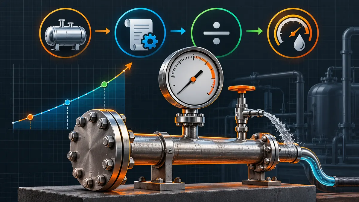
Key Terms
- Design Pressure (P)
- The internal pressure used as the basis for sizing a piping component, established by the process design.
- Maximum Allowable Working Pressure (MAWP)
- The maximum gauge pressure permissible at the top of a completed vessel in its normal operating position at a designated temperature.
- Hydrostatic Test
- A pressure test performed with an incompressible liquid, normally water, to verify structural integrity before service.
- Pneumatic Test
- A pressure test performed with a compressible gas, used only where a hydrostatic test is impractical.
- Allowable Stress (S)
- The maximum stress a material is permitted to carry at a given temperature, as tabulated in the governing code.
- Stress Ratio (St / Sd)
- The ratio of allowable stress at test temperature to allowable stress at design temperature, used to correct the test pressure for temperature-dependent strength.
- Hold Time
- The minimum duration the test pressure must be maintained to allow a complete visual inspection of all joints.
Frequently Asked Questions
What is the minimum hydrotest pressure required by ASME B31.3?
ASME B31.3 requires a minimum hydrostatic test pressure of 1.5 times the design pressure, adjusted by the ratio of allowable stress at test temperature to allowable stress at design temperature. Where the ratio is close to 1.0, the test pressure simplifies to roughly 1.5 times the design pressure.
How is the ASME Section VIII Division 1 hydrostatic test pressure calculated?
Per UG-99, the minimum hydrostatic test pressure for a Section VIII Division 1 vessel is 1.3 times the maximum allowable working pressure (MAWP), multiplied by the ratio of allowable stress at test temperature to allowable stress at design temperature.
What is the difference between hydrostatic and pneumatic test pressure factors?
Hydrostatic tests use a higher factor, 1.5 times design pressure for B31.3 or 1.3 times MAWP for Section VIII Division 1, because water stores little energy if a failure occurs. Pneumatic tests use a lower factor, typically 1.1 times, because compressed gas releases far more energy at failure and carries higher risk.
Can hydrotest pressure exceed the yield strength of the material?
No. Both ASME B31.3 and Section VIII Division 1 limit how the stress ratio may be applied so that the resulting test stress stays within a safe margin of the material’s yield strength at test temperature. If a calculated ratio would push the test pressure too high, the code-specified limit governs instead, and this should be verified against the applicable code edition.
What is the minimum hold time for a hydrotest?
The hold time must be long enough to allow a complete visual examination of every joint, weld, and connection in the test section. Project specifications commonly set a specific minimum duration at full test pressure in addition to the code’s general requirement for a thorough inspection.
Is a pneumatic test allowed instead of a hydrostatic test?
Pneumatic testing is permitted where a hydrostatic test is impractical, for example where the system cannot tolerate residual moisture or cannot support the weight of a liquid fill. Because pneumatic testing stores more energy, both ASME B31.3 and Section VIII Division 1 require additional precautions and often prior approval before it replaces a hydrostatic test.
Does static head need to be added to the calculated test pressure?
Where the elevation difference between the test gauge and the highest or lowest point of the system is significant, the test pressure must be corrected for the static head of the test liquid so that every point in the system experiences the intended test pressure, without over-testing the lowest elevation or under-testing the highest.
Standards and References
- ASME B31.3, Process Piping, American Society of Mechanical Engineers – governing hydrostatic and pneumatic test requirements for process piping.
- ASME Boiler and Pressure Vessel Code, Section VIII, Division 1, American Society of Mechanical Engineers – paragraphs UG-99 (hydrostatic test) and UG-100 (pneumatic test) for pressure vessels.
- ASME B31.1, Power Piping, American Society of Mechanical Engineers – test requirements for power piping systems.
Conclusion
Hydrotest pressure is not a single fixed multiplier you can apply blindly. It starts with the design pressure or MAWP, applies the code-specific factor for the equipment type (1.5 for B31.3 piping, 1.3 for Section VIII Division 1 vessels), and then corrects for the allowable stress ratio between test and design temperature. Getting each of these three inputs right, and checking them against the exact code edition your project references, is what separates a defensible test pack from a rework order. Use the calculator above for a fast first pass, then verify the result and any stress ratio limit against your project’s governing code edition before issuing the test pressure for field execution. For related calculations, see the PREN calculator on WeldFabWorld for materials selection in corrosive service, or the welding consumable selection guide for filler metal matched to the base materials being pressure tested.
About This Guide: This article was prepared by the WeldFabWorld technical team from the ASME codes listed in the References section above. Requirements vary by code edition and project specification; verify the current formulas, clause numbers, and stress ratio limits against the specific edition referenced in your project’s contract documents before use.