Tube-to-Tubesheet Welding: Joint Types, Procedure, and Qualification
Last updated:
Quick Answer: Tube-to-tubesheet welding joins heat exchanger tubes to the tubesheet with a strength weld, a seal weld, or a seal weld combined with mechanical expansion. Strength welds are qualified as full-penetration groove welds; seal welds may qualify under fillet weld rules. Where the construction code requires it, ASME Section IX QW-193 mock-up qualification applies instead, using dummy tubes welded into a representative tubesheet segment.
Tube-to-tubesheet welds are among the most numerous, and often the most inspected, welds on a shell-and-tube heat exchanger. A single exchanger bundle can carry hundreds or thousands of individual tube joints, each one a potential leak path between the tube side and shell side fluids. Get the joint design or the welder qualification wrong on even a small percentage of them, and the rework during hydrotest or in-service leak detection can consume the entire fabrication schedule.
This guide covers the two governing tube-to-tubesheet welding joint families defined in ASME BPVC Section VIII Division 1 (strength weld and seal weld), the GTAW procedure used to make them, and the ASME Section IX qualification path under QW-193 and QW-202, including when the code requires a physical mock-up instead of a standard groove or fillet weld qualification.
- ASME Section VIII Division 1, Figure UW-20.1 defines the acceptable tube-to-tubesheet weld joint configurations for strength welds.
- A strength weld carries the full pressure and mechanical load of the joint; a seal weld only prevents leakage while the tube is held by mechanical expansion.
- Autogenous GTAW (no filler metal) is the dominant process for tube-to-tubesheet welding due to the small, repetitive joint geometry.
- ASME Section IX QW-193 requires a mock-up of at least 10 tubes for procedure qualification and at least 5 tubes per welder for performance qualification, when the construction code calls for mock-up qualification.
- Where mock-up qualification is not mandated, QW-202.6 permits qualifying tube-to-tubesheet welds as a groove weld or, for non-pressure-retaining seal welds, as a fillet weld under QW-202.2(c).
What Is Tube-to-Tubesheet Welding?
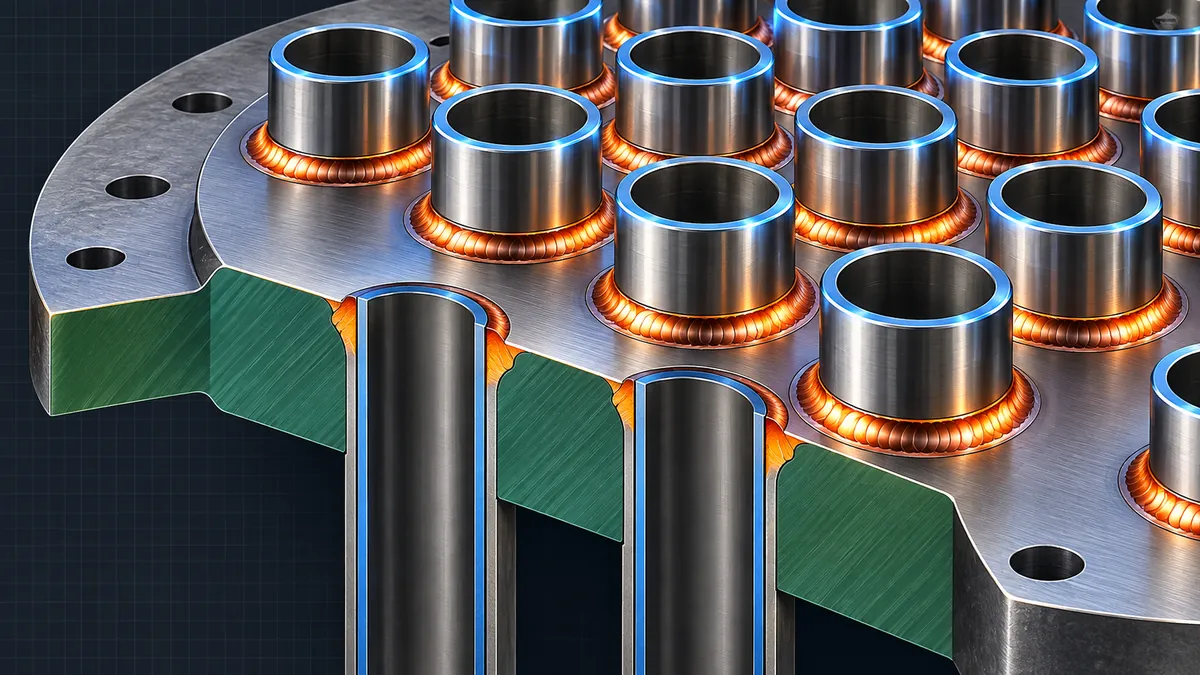
Tube-to-tubesheet welding is the joining of heat exchanger tube ends to the drilled holes of a tubesheet, using a fusion weld to seal or structurally connect each tube in place of, or in addition to, mechanical expansion. The joint sits at the boundary between the tube side and shell side fluids, so its integrity directly determines whether the two fluid streams stay separated for the life of the equipment.
Two governing documents shape almost every tube-to-tubesheet weld made in the pressure equipment industry: ASME BPVC Section VIII Division 1, which defines the acceptable joint configurations for pressure vessels and heat exchangers (Figure UW-20.1 and related paragraphs under UW-20), and TEMA (Tubular Exchanger Manufacturers Association) standards, which are widely referenced for exchanger design details even where ASME governs the pressure boundary. On the welding side, ASME Section IX governs how the welding procedure and the welders themselves are qualified for this joint type.
Why it is treated as a special joint: A tube-to-tubesheet weld is neither a conventional butt weld nor a conventional fillet weld. The tube wall is thin (commonly 1.65 mm to 3.4 mm), the joint is highly repetitive across a tightly pitched tube pattern, and access is often limited to one side. ASME Section IX recognizes this by giving tube-to-tubesheet welds a dedicated qualification path rather than folding them entirely into ordinary groove or fillet weld rules.
What Joint Types Are Used for Tube-to-Tubesheet Welds?
ASME Section VIII Division 1 recognizes two functional categories of tube-to-tubesheet weld, both illustrated in Figure UW-20.1 with several acceptable groove configurations:
Strength Weld
A strength weld is a full-penetration groove weld sized to carry the full pressure and mechanical load transferred between the tube and the tubesheet, without relying on mechanical expansion for load capacity. The groove weld leg size is established per UW-20.6, based on the tube wall thickness and the joint configuration selected. Strength welds are qualified as groove welds under Section IX.
Seal Weld
A seal weld is a lighter, typically fillet-type weld whose only function is to prevent leakage at the tube end; the mechanical strength of the joint is provided separately, usually by roller or hydraulic expansion of the tube into the tubesheet hole. Where a seal weld is non-pressure-retaining by design intent, it may be qualified under the fillet weld provisions of QW-202.2(c).
| Aspect | Strength Weld | Seal Weld |
|---|---|---|
| Load-carrying role | Carries full pressure and mechanical load | None; leak barrier only |
| Typical geometry | Full-penetration groove weld | Fillet-type weld around tube projection |
| Requires tube expansion | Often still expanded for crevice control design dependent | Yes, expansion provides the mechanical grip |
| Section IX qualification route | Groove weld (QW-202) or QW-193 mock-up | Fillet weld (QW-202.2(c)) or QW-193 mock-up |
| Governing ASME VIII clause | UW-20(b), Figure UW-20.1 | UW-20(c) |
Caution: Some purchaser specifications require roller or hydraulic expansion of every tube even when the joint is strength welded, to close the annular gap between the tube outside diameter and the tubesheet hole. This protects against shell-side crevice corrosion at the tube-to-tubesheet interface and is a project-specific requirement, not a universal code mandate, so it must be confirmed against the applicable specification.
Welding Plus Mechanical Expansion
Most tube-to-tubesheet joints, strength welded or seal welded, are also mechanically expanded, either by roller expansion or hydraulic expansion, after welding. Expansion serves several purposes beyond load transfer on seal-welded joints:
- Closes the annular clearance between the tube outside diameter and the tubesheet hole, reducing the crevice available for shell-side corrosion.
- Provides additional resistance to tube vibration between the tubesheet and the first support baffle.
- On strength-welded joints designed per ASME Section VIII Division 1 Part UHX, the depth of expansion can be credited in the tubesheet thickness calculation.
- Reduces the load carried by the weld alone in service, extending fatigue life under thermal cycling.
Expansion is typically performed to a specified percentage of wall reduction or a specified torque, and is normally done after welding so the weld is not disturbed by the expansion tooling.
Welding Process and Procedure
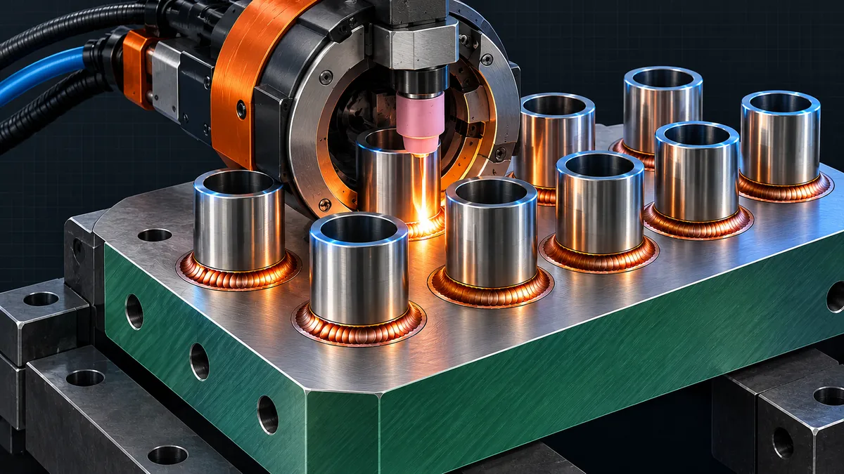
Gas Tungsten Arc Welding (GTAW), almost always autogenous (without filler metal), is the dominant process for tube-to-tubesheet welding. The small joint size, the need for a smooth, controllable arc, and the requirement for a clean, oxide-free weld all favor GTAW over higher heat input processes such as Shielded Metal Arc Welding (SMAW) or Gas Metal Arc Welding (GMAW).
Typical Procedure Sequence
- Hole and tube preparation. Tubesheet holes are drilled and, where specified, grooved to the tolerance required by the joint design; tube ends are cleaned and deburred immediately before welding.
- Fit-up and tube projection. Tubes are inserted to the specified projection above the tubesheet face and checked for concentricity within the hole.
- Tack or root pass. A light root pass fuses the tube to the tubesheet face or groove, using an orbital or manual GTAW head depending on the level of automation.
- Fill passes (strength welds only). Additional passes build the groove weld to the specified leg size determined under UW-20.6.
- Visual and dimensional check. Each completed weld is visually examined for uniform profile, absence of undercut, and correct leg size before the bundle moves to expansion and non-destructive examination.
Field tip: Orbital GTAW heads with programmable current profiles produce far more consistent tube-to-tubesheet welds than manual TIG on high-tube-count bundles, because the weld parameters do not drift between the hundredth tube and the first. Manual welding is still common on repair work, low tube-count bundles, or joint geometries the orbital head cannot reach.
How Are Tube-to-Tubesheet Welds Qualified (ASME Section IX)?
ASME Section IX gives tube-to-tubesheet welding two possible qualification routes, and which one applies depends on the construction code and the purchaser specification for the equipment:
Route 1: Groove or Fillet Weld Qualification (QW-202.6)
Where the construction code does not mandate a physical mock-up, QW-202.6 allows a strength weld to be qualified as a conventional groove weld under QW-202, and a non-pressure-retaining seal weld to be qualified as a fillet weld under QW-202.2(c). This route uses a test plate rather than a tube-and-tubesheet mock-up, and is generally the simpler and lower-cost path where it is permitted.
Route 2: Mock-Up Qualification (QW-193)
Where the construction code requires it (for example, under ASME Section VIII Division 1 paragraph UW-28(b), which directs the user to qualify under QW-193 or QW-200), the procedure and the welder must be qualified using a mock-up that reproduces the actual production joint: the same tubesheet material, the same tube material and diameter, the same joint design, and the same tube pitch and spacing as the equipment being fabricated.
Why the routes diverge: A tube-to-tubesheet weld behaves differently from a flat-plate groove weld because of the restraint of the surrounding tubesheet mass, the confined access, and the effect of adjacent tube holes on heat dissipation. QW-193 mock-up qualification exists specifically to prove the welder and the procedure can reproduce a sound weld under those real joint conditions, not just under open, flat-plate conditions.
The QW-193 Mock-Up Procedure
When mock-up qualification applies, ASME Section IX QW-193 sets out specific requirements distinct from standard groove weld qualification:
| Requirement | Procedure Qualification | Welder / Operator Qualification |
|---|---|---|
| Minimum mock-up tubes | 10 tubes (commonly cited industry practice) | Minimum 5 tubes per welder (QW-193.2) |
| Mock-up construction | Represents the actual joint design, materials, and tube pitch | Same as procedure qualification rules |
| Examination method | Visual, liquid penetrant, and macro-etch examination (QW-193.1 to QW-193.1.3) | Same examination methods applied |
| Sectioning | Mock-up welds sectioned through the tube center for macro-examination | Same |
| Essential variables | Per QW-288 (tube-to-tubesheet specific variable list) | Per QW-288 performance variables |
The mock-up tubesheet segment should reasonably represent the production tubesheet, including material and, for clad tubesheets, a base material with a composition essentially equivalent to the cladding, since heat-affected zone behavior in the mock-up needs to be representative of what will actually happen in production.
Caution: A mock-up qualified on a thin dummy tubesheet does not necessarily qualify the welder or procedure for a thick production tubesheet, and vice versa, because tubesheet mass strongly affects heat dissipation during welding. Match the mock-up tubesheet thickness and material to the production joint as closely as practicable.
Inspection and Acceptance
Production tube-to-tubesheet welds are typically subject to a combination of the following examinations, with the exact scope set by the purchaser specification and the construction code:
- Visual examination of every weld for uniform profile, complete fusion at the visible toe, and absence of surface cracking or undercut.
- Liquid penetrant examination where surface-breaking defects must be positively ruled out, particularly on strength welds and on austenitic or duplex stainless materials.
- Pneumatic or hydrostatic leak testing of the completed tube bundle, often using a shell-side air or helium test to detect even minor tube-to-tubesheet leakage before the bundle is closed into its shell.
- Hardness testing on the mock-up, particularly relevant for hardening materials such as duplex stainless steel or titanium, or where sour service places a hardness limit on the weld.
Because access to a leaking tube-to-tubesheet joint after the bundle is in service is difficult and costly, this inspection scope is rarely reduced below the specification minimum, even on schedule-critical projects.
Quick Reference: Joint Type vs Qualification Route
| Joint Type | ASME VIII Div. 1 Basis | Section IX Route (if code allows QW-202.6) | Section IX Route (if mock-up required) |
|---|---|---|---|
| Strength weld | UW-20(b), Figure UW-20.1, leg size per UW-20.6 | Groove weld, QW-202 | QW-193 mock-up |
| Seal weld (non-pressure-retaining) | UW-20(c) | Fillet weld, QW-202.2(c) | QW-193 mock-up |
| Seal weld with filler (hybrid) | Per purchaser specification | Depends on design intent; confirm with the design authority | QW-193 mock-up |
Common Mistakes and Limitations
- Assuming plate or pipe WPS coverage applies. A welding procedure qualified on flat plate or pipe does not automatically cover tube-to-tubesheet welding; the joint geometry and heat sink effect of the tubesheet are different enough that Section IX treats it as a separate qualification.
- Under-sizing the mock-up tubesheet. A mock-up made from thin scrap plate rather than a representative tubesheet thickness can qualify a welder for conditions that do not match production heat dissipation.
- Confusing seal welds with strength welds in design intent. A seal weld is not sized or qualified to carry mechanical load; treating it as load-bearing in service is a design error, not a welding error, and must be caught at the design stage.
- Skipping expansion after strength welding. Even where the weld alone is adequate for pressure retention, omitting the specified expansion can leave a crevice that drives shell-side corrosion over the exchanger’s service life.
- Treating orbital GTAW as inherently code-compliant. Automated welding equipment still requires the underlying procedure and, where applicable, operator to be qualified under the same Section IX rules as manual welding.
Requirements depend on the code edition and the contract specification applicable to your project; confirm the current edition’s exact paragraph numbers and mock-up quantities before finalizing a qualification plan.
Key Terms
- Tubesheet
- The thick perforated plate that separates the tube side and shell side of a heat exchanger and anchors the tube ends.
- Strength Weld
- A tube-to-tubesheet weld designed and sized to carry the full pressure and mechanical load of the joint.
- Seal Weld
- A tube-to-tubesheet weld intended only to prevent leakage, with mechanical strength provided by tube expansion.
- Autogenous GTAW
- Gas Tungsten Arc Welding performed without the addition of filler metal, common for thin tube-to-tubesheet joints.
- Mock-Up Qualification
- Qualification of a welding procedure or welder using a test assembly that reproduces the actual production joint design, per ASME Section IX QW-193.
- Tube Expansion
- Mechanical enlargement of the tube outside diameter against the tubesheet hole, by roller or hydraulic methods, to improve joint tightness and load transfer.
- TEMA
- Tubular Exchanger Manufacturers Association, whose standards are widely referenced for shell-and-tube heat exchanger design details.
Frequently Asked Questions
What is the difference between a strength weld and a seal weld on a tubesheet?
A strength weld is a full-penetration groove weld designed to carry the full pressure and mechanical load of the tube-to-tubesheet joint on its own. A seal weld is a lighter weld, typically fillet-type, whose only function is to prevent leakage; the mechanical strength of the joint comes from mechanical expansion of the tube into the tubesheet hole rather than from the weld.
Does tube-to-tubesheet welding always require a mock-up under ASME Section IX?
Not always. Mock-up qualification under QW-193 is required only where the construction code, such as ASME Section VIII Division 1, mandates it. Where it is not mandated, QW-202.6 allows qualification as a standard groove weld for strength welds or a fillet weld under QW-202.2(c) for non-pressure-retaining seal welds.
How many mock-up tubes are needed to qualify a tube-to-tubesheet welding procedure?
Industry practice under QW-193 typically uses a minimum of ten mock-up tube welds for procedure qualification and a minimum of five mock-up tube welds for each welder or welding operator performance qualification, examined by visual, liquid penetrant, and macro-etch methods.
Why is GTAW the preferred process for tube-to-tubesheet welding?
Gas Tungsten Arc Welding, usually without filler metal, gives the controllable, low heat input arc needed for the thin tube wall and small, tightly pitched joint geometry typical of tube-to-tubesheet welds. Automated orbital GTAW heads also produce far more consistent results across the large number of repetitive joints on a typical tube bundle than manual welding with higher heat input processes.
Is tube expansion required in addition to welding?
Expansion requirements depend on the joint type and the purchaser specification. Seal-welded joints require expansion to provide mechanical strength, since the weld alone does not. Strength-welded joints may still be expanded to close the annular clearance and reduce shell-side crevice corrosion risk, even though the weld itself is designed to carry the load.
What examinations are typically performed on tube-to-tubesheet welds?
Production welds are commonly visually examined on every joint, with liquid penetrant examination applied where surface defects must be positively ruled out. Completed tube bundles are typically leak tested, often with a shell-side pneumatic or hydrostatic test, to confirm every tube-to-tubesheet joint is sound before the bundle is closed into service.
Can a welding procedure qualified on flat plate be used for tube-to-tubesheet welding?
No. Tube-to-tubesheet welding is treated as a distinct joint category under ASME Section IX because the restraint of the surrounding tubesheet mass and the confined joint access behave differently from an open flat-plate groove weld. A procedure must be separately qualified for tube-to-tubesheet welding, either as a groove or fillet weld under QW-202.6 or through QW-193 mock-up qualification where required.
Standards and References
- ASME Boiler and Pressure Vessel Code, Section VIII, Division 1, American Society of Mechanical Engineers – paragraph UW-20 and Figure UW-20.1, tube-to-tubesheet joint configurations and strength weld sizing (UW-20.6).
- ASME Boiler and Pressure Vessel Code, Section IX, American Society of Mechanical Engineers – QW-193 (tube-to-tubesheet mock-up qualification), QW-202 and QW-202.2(c) (groove and fillet weld qualification), QW-288 (tube-to-tubesheet essential variables).
- TEMA (Tubular Exchanger Manufacturers Association) Standards – widely referenced for shell-and-tube heat exchanger design and tube-to-tubesheet joint detail.
Conclusion
Tube-to-tubesheet welding sits at the intersection of joint design and welder qualification in a way few other weld types do. Choosing between a strength weld and a seal weld is a design decision that determines whether mechanical expansion is load-bearing or supplementary; qualifying the procedure and the welder correctly under ASME Section IX, whether through QW-202.6 or a full QW-193 mock-up, is what makes that design decision defensible on paper and reliable in the field. With hundreds of joints per bundle and limited access once the equipment is in service, getting the joint type and qualification route right the first time is far cheaper than any repair campaign after commissioning. For related qualification topics, see the Welder Qualification (WPQ) guide on WeldFabWorld, and for material selection guidance on the tubesheet and tube materials themselves, see the welding consumable selection guide.
About This Guide: This article was prepared by the WeldFabWorld technical team from the ASME codes listed in the References section above. Requirements vary by code edition and project specification; verify the current edition’s exact paragraph numbers, mock-up quantities, and acceptance criteria against the specific edition referenced in your project’s contract documents before use.