High-Temperature Material Properties for Welding
Last updated:
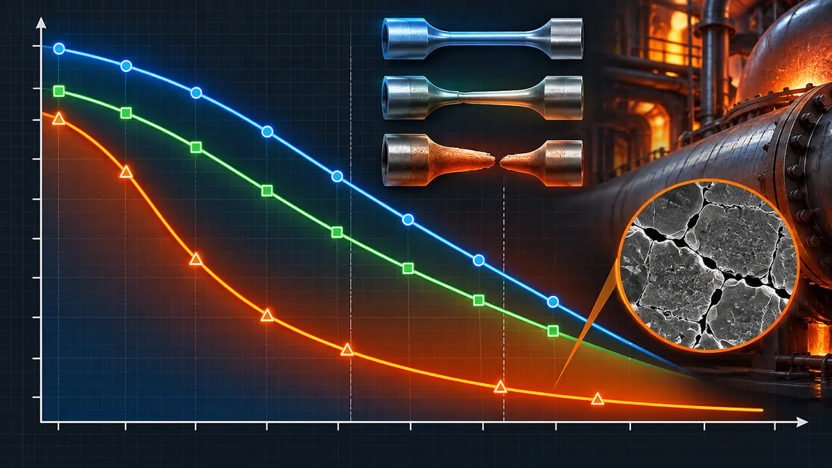
Quick Answer: As temperature rises, a material’s yield and tensile strength fall while its tendency to creep, a slow time-dependent stretching under constant load, increases. Below roughly 350-450°C for ferritic steels, allowable stress is governed by short-term yield and tensile strength. Above that range, allowable stress is instead governed by long-term creep rupture strength, which is why ASME material tables show a distinct break in behavior and why welded joints in that service range need creep-aware design and PWHT.
A material data sheet gives one number for yield strength and one for tensile strength, both measured at room temperature. Neither number tells you how that material will behave welded into a furnace tube, a steam header, or a hot process line running at 450°C or 550°C for twenty years. High-temperature material properties for welding is the discipline of understanding what actually governs strength and failure once a component leaves the room-temperature regime and enters the time-dependent, creep-controlled regime that dominates power, refining, and petrochemical plant design.
This guide walks through what happens to strength, ductility, and toughness as temperature rises, where the transition from strength-controlled to creep-controlled design happens for common pressure equipment materials, and what that transition means for welding procedure selection, heat-affected zone behavior, and post-weld heat treatment.
- Yield strength falls faster than tensile strength as temperature rises, narrowing the margin between the two.
- Creep, the slow, time-dependent deformation of a material under a sustained load below its yield strength, becomes significant once temperature exceeds roughly 30 to 40 percent of the material’s absolute melting temperature.
- Design codes switch the basis for allowable stress from short-term tensile and yield properties to long-term creep rupture strength once a material enters its creep range, typically noted by italicized or flagged values in ASME stress tables.
- Alloying with chromium and molybdenum raises the temperature at which a steel enters the creep range, which is why Cr-Mo steels like P11, P22, and P91 replace carbon steel in hot service.
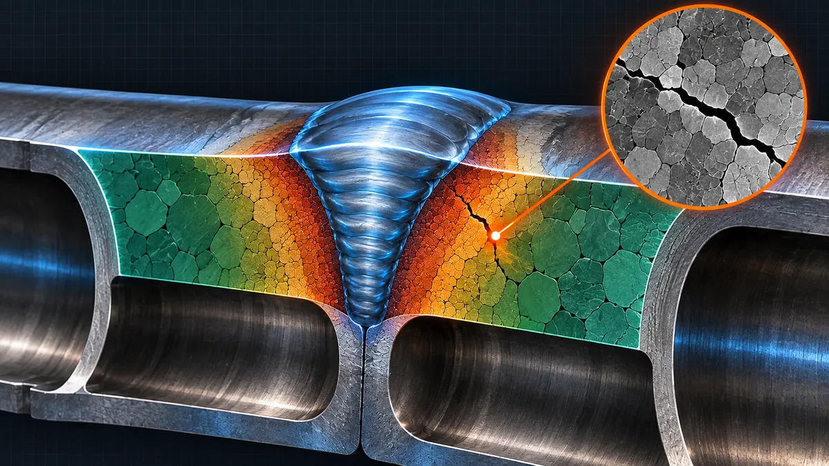
- The weld metal, heat-affected zone, and base metal of a welded joint can each have different creep strength, and the weakest of the three, often the HAZ, typically governs long-term joint life.
What Changes in a Material at High Temperature?
High-temperature material behavior is the combination of reduced yield and tensile strength, increased ductility in most steels, and the onset of time-dependent creep deformation, all of which change how a material must be designed and welded compared to room temperature.
Four properties move in a predictable direction as temperature rises for most structural and pressure-vessel steels:
- Yield strength decreases steadily, and generally decreases faster in percentage terms than tensile strength.
- Tensile strength also decreases, though for some steels it can dip and briefly rise again in an intermediate range due to strain aging effects before falling again at higher temperature.
- Ductility often decreases in an intermediate temperature band (sometimes called the blue-brittle range for carbon steels, roughly 200 to 300°C) before increasing again at higher temperatures.
- Creep resistance is not meaningfully present at room temperature but becomes the dominant, and eventually the only, design consideration as temperature climbs into a material’s creep range.
Why yield strength alone stops being useful: At room temperature, a load held below yield strength produces essentially no further deformation over time. At elevated temperature, the same load held below yield strength can still cause the material to slowly stretch and eventually rupture, because atoms are mobile enough to allow slow, sustained plastic flow. This is the fundamental reason high-temperature design cannot rely on yield strength alone.
What Is Creep and When Does It Matter?
Creep is the slow, time-dependent plastic deformation of a material under a constant load, at a stress that can be well below its yield strength, occurring because atomic diffusion becomes significant at elevated temperature. A component that appears perfectly adequate on a short-term tensile test can still creep to failure over months or years in service if the combination of stress and temperature is high enough.
Creep becomes practically significant once the operating temperature exceeds roughly 30 to 40 percent of the material’s absolute melting temperature, a threshold often called the homologous temperature. Because different alloys melt at different temperatures, this threshold is not a single number in degrees Celsius; it shifts with alloy content, which is exactly why alloying with chromium, molybdenum, and other elements is used specifically to push a steel’s creep range to a higher service temperature.
The Three Stages of Creep
- Primary (transient) creep: deformation rate starts relatively high and decreases as the material work-hardens.
- Secondary (steady-state) creep: deformation rate stabilizes at a roughly constant minimum rate; this stage is used as the basis for most long-term design life calculations.
- Tertiary creep: deformation rate accelerates as internal damage (voiding, grain boundary cavitation) accumulates, ending in rupture.
Design implication: Because secondary creep rate is the most predictable stage, high-temperature design life is commonly based on a target minimum creep rate or a target rupture life (for example, a stress that produces a defined percentage of creep strain, or causes rupture, over a stated design life such as 100,000 hours), rather than on a simple safety factor against room-temperature yield strength.
How Does Temperature Change Allowable Stress?
Design codes such as ASME Section II Part D and ASME B31.3 tabulate allowable stress for each material at a series of temperatures. At lower temperatures, the allowable stress is based on a margin against the material’s short-term tensile and yield strength. Once the material’s temperature enters its creep range, the code instead bases allowable stress on long-term creep and rupture data: typically the stress that produces a specified minimum creep rate, and the stress that causes rupture over a specified design life, with the lower of the relevant criteria governing.
This is why allowable stress tables often show a visibly different rate of decline above a certain temperature for a given material, and why some codes flag values in that range (for example, with italics or a footnote) to warn the user that the value is time-dependent rather than based on short-term strength alone.
Caution: Always use the allowable stress value for the specific temperature and specific edition of the code referenced by your project. Interpolating loosely between temperature points, or using a value from a different code edition, can materially understate or overstate the actual margin available, particularly inside the creep range where the stress-temperature curve is not linear.
Material Families and Their Creep Range
Different material families enter their creep-controlled design regime at different temperatures, which is the primary reason a specific alloy is selected for a specific process temperature:
| Material Family | Typical Creep-Range Onset | Common Application |
|---|---|---|
| Carbon steel | Approximately 350-400°C | General process piping, low-temperature vessels |
| C-1/2Mo, 1-1/4Cr-1/2Mo (P11) | Somewhat higher than carbon steel | Moderate-temperature refinery piping |
| 2-1/4Cr-1Mo (P22) | Higher again, well into the 450-500°C range | Hydroprocessing reactors, hot piping |
| 9Cr-1Mo-V (P91) | Extends usefully to roughly 600°C | Ultra-supercritical power piping, high-temperature headers |
| Austenitic stainless steel (300 series) | Generally higher than ferritic steels of similar era | High-temperature corrosive or oxidizing service |
| Nickel-based alloys | Highest of common structural alloys | Extreme high-temperature or highly corrosive service |
The general trend is consistent: increasing chromium and molybdenum content raises the temperature at which time-dependent creep behavior starts to dominate over short-term strength, which is exactly why Cr-Mo alloy steels replace carbon steel as design temperature climbs, and why nickel-based alloys are reserved for the most demanding combinations of temperature and corrosive environment.
What Does This Mean for Welded Joints?
A welded joint is not metallurgically uniform. It consists of weld metal, a heat-affected zone (HAZ) with a range of microstructures produced by the thermal cycle of welding, and unaffected base metal, each of which can have different high-temperature strength:
- Filler metal matching: Filler metal composition is selected not only to match room-temperature strength but to provide adequate creep strength at the intended service temperature; a filler that matches tensile strength at room temperature will not necessarily match creep rupture strength at 550°C.
- Post-weld heat treatment: PWHT is frequently mandatory on Cr-Mo and other creep-service alloys specifically to temper the as-welded microstructure into a more stable, more creep-resistant condition before the component enters service.
- Preheat and interpass control: Controlling cooling rate through welding parameters affects the final HAZ microstructure, which in turn affects long-term creep performance, not just short-term hardness or hydrogen cracking risk.
- Dissimilar metal welds: Where a creep-resistant alloy is welded to a lower-alloy material, the mismatch in creep strength across the joint, and the differential thermal expansion during service thermal cycling, both require specific design and filler metal selection attention.
HAZ Softening and Type IV Cracking
Two failure patterns specific to welded joints in creep service deserve particular attention:
HAZ Softening
In some Cr-Mo alloys, particularly 9Cr-1Mo-V (P91) and similar creep-strength-enhanced ferritic steels, a region of the heat-affected zone can end up with lower creep strength than either the weld metal or the unaffected base metal, because the welding thermal cycle alters the fine precipitate structure that gives these steels their creep resistance. This softened band can become the weakest link in the joint under long-term service, even though it may look unremarkable on a standard hardness survey shortly after fabrication.
Type IV Cracking
Type IV cracking is a creep-driven failure mode that initiates specifically in the fine-grained region of the HAZ of creep-strength-enhanced ferritic steel welds, appearing after extended service rather than shortly after fabrication or PWHT. It is a recognized long-term integrity concern on P91 and similar alloys and is a key reason why welding procedure qualification, PWHT control, and in-service inspection planning for these materials receive close attention from the design and integrity engineering community.
Caution: Type IV cracking is a long-term, service-life phenomenon. It is not detected by standard post-weld NDT or by short-term mechanical testing during procedure qualification, which is why creep-strength-enhanced ferritic steel welds in high-temperature service are typically subject to specific inspection and monitoring programs over the life of the equipment.
Quick Reference: Property Regime by Temperature
| Temperature Band | Governing Property | Design Basis |
|---|---|---|
| Room temperature to moderate | Yield strength, tensile strength | Short-term mechanical properties with a code-specified margin Strength-controlled |
| Intermediate (material-dependent) | Ductility minimum (blue-brittle range for carbon steels) | Still strength-controlled, but toughness and strain aging need attention Transition |
| Above creep-range onset | Creep rupture strength, minimum creep rate | Long-term, time-dependent data governs allowable stress Creep-controlled |
Common Mistakes and Limitations
- Using room-temperature yield strength as the sole design check at elevated temperature. Once a component operates in the creep range, a design that is adequate against short-term yield strength can still fail by creep rupture over the service life.
- Treating filler metal selection as a room-temperature strength-matching exercise only. A filler that matches base metal strength at room temperature does not automatically match creep strength at service temperature; filler metal selection for creep service should be verified against the intended operating temperature.
- Skipping or shortening PWHT on creep-service alloys to save schedule. PWHT on many Cr-Mo alloys is not just about hydrogen removal or distortion control; it also stabilizes the microstructure into a condition with predictable long-term creep behavior.
- Assuming Type IV cracking will show up in post-weld inspection. This is a long-term, in-service degradation mode; it is not detected by standard post-fabrication NDT and needs a dedicated inspection strategy over the equipment’s operating life.
- Ignoring dissimilar creep-strength mismatch at transition welds. Welding a creep-strength-enhanced alloy to a lower-alloy material creates a joint where the weaker material, not the stronger one, sets the long-term capability of the connection.
Requirements and specific temperature thresholds depend on the material grade, the code edition, and the design life specified for the equipment; always confirm actual allowable stress values and creep-range boundaries against the specific code and material specification governing your project.
Key Terms
- Creep
- Slow, time-dependent plastic deformation of a material under a sustained load at elevated temperature, occurring even at stress below the material’s yield strength.
- Creep Rupture Strength
- The stress that causes a material to fail by creep over a specified design life at a given temperature.
- Allowable Stress
- The maximum stress a material is permitted to carry under a design code, based on the governing short-term or long-term property at the design temperature.
- Homologous Temperature
- The ratio of the absolute service temperature to the material’s absolute melting temperature, used as a general indicator of when creep becomes significant.
- HAZ Softening
- A localized reduction in strength, particularly creep strength, in part of the heat-affected zone of a weld, caused by the welding thermal cycle altering the material’s microstructure.
- Type IV Cracking
- Creep-driven cracking that initiates in the fine-grained heat-affected zone of creep-strength-enhanced ferritic steel welds, appearing after extended high-temperature service.
- Minimum Creep Rate
- The steady-state rate of deformation during secondary creep, commonly used as a basis for long-term design stress limits.
Frequently Asked Questions
What is the difference between yield strength and creep rupture strength as design criteria?
Yield strength describes the stress at which a material begins to deform plastically in a short-term test and is time-independent. Creep rupture strength describes the stress that causes a material to fail after a specified length of time at a given temperature, and only becomes the governing design criterion once a component operates in the material’s creep-controlled temperature range.
At what temperature does creep become a design concern for carbon steel?
Creep typically becomes a practical design concern for carbon steel at approximately 350 to 400 degrees Celsius, though the exact threshold depends on the specific grade and the design code’s allowable stress tables. Above this range, allowable stress is based on long-term creep and rupture data rather than short-term tensile and yield properties alone.
Why do Cr-Mo steels replace carbon steel in high-temperature service?
Chromium and molybdenum alloying raises the temperature at which a steel’s creep resistance remains adequate, extending the useful service temperature range well beyond that of plain carbon steel. This is why grades such as P11, P22, and P91 are selected for progressively higher-temperature piping and pressure vessel applications where carbon steel would enter its creep-controlled regime too early for an economical design life.
What is Type IV cracking and why does it matter for welded joints?
Type IV cracking is a creep-driven cracking mode that initiates in the fine-grained heat-affected zone of creep-strength-enhanced ferritic steel welds, such as P91, appearing after extended high-temperature service rather than immediately after fabrication. It matters because it is not detectable by standard post-weld inspection and requires a dedicated long-term inspection and integrity management strategy.
Does post-weld heat treatment improve high-temperature performance?
Yes, on many creep-service alloys. Beyond relieving residual stress and reducing hydrogen cracking risk, PWHT tempers the as-welded microstructure into a more stable condition that behaves more predictably under long-term creep loading, which is why it is frequently a mandatory step on Cr-Mo and similar high-temperature alloy welds.
Can filler metal be selected purely on room-temperature strength matching?
Not for creep service. A filler metal that matches the base metal’s room-temperature tensile strength does not automatically provide equivalent creep rupture strength at the intended service temperature. Filler metal selection for high-temperature service should be verified against the actual operating temperature and design life, not room-temperature strength alone.
What is the homologous temperature and why does it matter?
Homologous temperature is the ratio of a material’s absolute service temperature to its absolute melting temperature. Creep generally becomes significant once this ratio exceeds roughly 0.3 to 0.4, which is why different alloys enter their creep-controlled regime at different service temperatures in degrees Celsius, depending on their melting point and composition.
Standards and References
- ASME Boiler and Pressure Vessel Code, Section II, Part D, American Society of Mechanical Engineers – allowable stress tables by material and temperature, including creep-range values.
- ASME B31.3, Process Piping, American Society of Mechanical Engineers – allowable stress basis and application to piping design across the strength-controlled and creep-controlled temperature ranges.
- API 530, Calculation of Heater-Tube Thickness in Petroleum Refineries, American Petroleum Institute – creep-based design methodology for fired heater tubes.
Conclusion
High-temperature material behavior is not simply “the same properties, but weaker.” Below a material-specific threshold, design is governed by familiar short-term yield and tensile strength; above it, the governing property becomes long-term creep rupture strength, a fundamentally different, time-dependent failure mode that a short-term tensile test cannot reveal. For welded joints, this shift matters even more, because the weld metal, HAZ, and base metal can each respond differently to both the original welding thermal cycle and decades of subsequent creep exposure. Selecting the right alloy family, controlling PWHT, and understanding phenomena like HAZ softening and Type IV cracking are what separate a joint that survives its design life from one that fails quietly, years into service, at a stress well below its original yield strength. For related design inputs, see the hydrotest pressure calculator on WeldFabWorld, which uses the same allowable stress tables discussed here, and the reheat cracking guide for a related HAZ degradation mechanism in Cr-Mo steels.
About This Guide: This article was prepared by the WeldFabWorld technical team from the codes and standards listed in the References section above. Requirements, specific temperature thresholds, and allowable stress values vary by material grade and code edition; verify current values against the specific edition referenced in your project’s contract documents before use.