ASME Section VIII Division 1 — Complete Overview
ASME Section VIII Division 1 of the Boiler and Pressure Vessel Code (BPVC) is the most widely used pressure vessel fabrication code in the world. It provides mandatory rules for the design, materials, fabrication, examination, inspection, testing, and certification of pressure vessels operating at pressures above 15 psi (103 kPa). From small industrial heat exchangers to large refinery columns, the code governs the production of hundreds of thousands of vessels annually across the petrochemical, power generation, industrial gas, pharmaceutical, and food processing industries. Any welding engineer, fabrication inspector, or mechanical engineer working in the pressure equipment sector must have a working command of its requirements.
The code is published by the American Society of Mechanical Engineers (ASME) and is updated on a two-year cycle. It is mandatorily adopted by all U.S. states and Canadian provinces under their pressure vessel legislation, and is referenced or accepted as an equivalent standard by regulators in over 100 countries. Compliance with Division 1 is demonstrated by the application of the ASME U-stamp to the completed vessel nameplate, which certifies that the vessel was designed, fabricated, inspected, and tested in accordance with the code requirements in effect at the time of manufacture.
This article provides a complete technical overview of Section VIII Division 1: what it covers and what it excludes, how the code is structured, the design formulae for shells and heads, joint categories and efficiencies, allowable stress values, NDE requirements, MDMT, PWHT rules, pressure testing, and the U-stamp certification process. Where appropriate, key formulae are presented with worked examples.
Scope and Jurisdiction
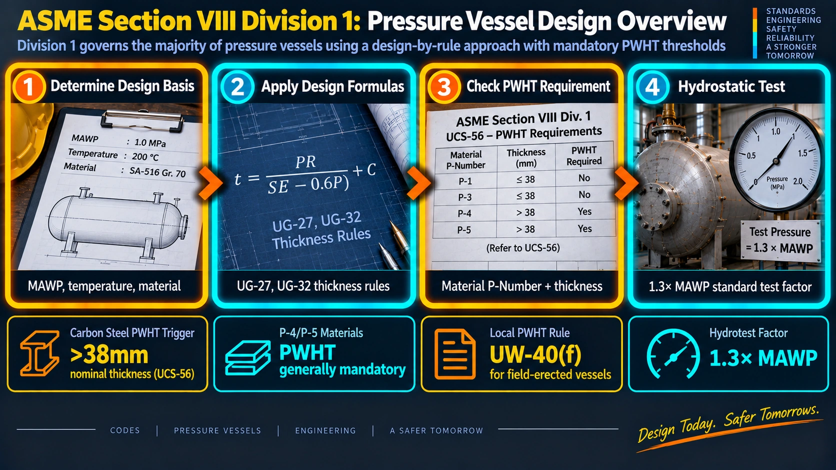
ASME Section VIII Division 1 applies to the design, fabrication, inspection, testing, and certification of pressure vessels operating at internal or external pressures exceeding 15 psi (103 kPa). The code covers a broad range of vessel types including heat exchangers, reactors, separators, distillation columns, storage vessels, air receivers, and any other closed container designed to contain pressurised fluid.
What Division 1 Covers
- Vessels fabricated by welding, brazing, or a combination thereof
- Vessels subject to internal pressure or external pressure (vacuum service)
- Fired and unfired pressure vessels
- Vessels in all industries: petrochemical, power, pharmaceutical, food and beverage, industrial gas, marine, and cryogenic service
- Vessels fabricated in any country, provided they meet the code requirements and are inspected by an Authorized Inspector
What Division 1 Excludes
The following categories are explicitly excluded from the scope of Section VIII Division 1 per UG-1:
- Vessels with design pressure at or below 15 psi (103 kPa)
- Vessels with inside diameter not exceeding 6 inches (152 mm) at any pressure
- Boilers subject to ASME Section I (Power Boilers) or Section IV (Heating Boilers)
- Pressure vessels for human occupancy (covered by separate standards)
- Vessels in nuclear power service (covered by ASME Section III)
- Piping systems, heat exchangers specifically covered by other codes (e.g. TEMA), and pressure parts of rotating equipment
- Vessels below the capacity and temperature combinations that individual state jurisdictions may exempt
Code Structure and Subsections
ASME Section VIII Division 1 is organised into three subsections (UG, UW, UB) plus a series of mandatory and non-mandatory appendices. The prefix letters indicate the scope of the rules:
| Prefix | Subsection / Part | Coverage |
|---|---|---|
| UG | General Requirements | Scope, materials, design, fabrication, inspection, testing, marking — applies to all vessels regardless of fabrication method |
| UW | Requirements for Welded Vessels | Joint design, weld categories, joint efficiencies, welding qualifications (referencing Section IX), NDE for welds, PWHT |
| UB | Requirements for Brazed Vessels | Brazing materials, procedure and performance qualification, inspection of brazed joints |
| UCS | Carbon and Low-Alloy Steel | Material-specific rules: impact testing exemption curves, MDMT, hardness limits after PWHT |
| UNF | Non-Ferrous Materials | Rules for aluminium, copper, nickel, titanium, and zirconium alloys |
| UHA | High-Alloy Steels | Rules for austenitic stainless steels and other high-alloy materials |
| UCI | Cast Iron | Restrictions on use of cast iron in pressure-containing parts |
| UCD | Cast Ductile Iron | Rules for ductile iron vessels |
| UHT | Ferritic Steels with Enhanced Tensile Properties | Quenched and tempered steels; additional impact testing requirements |
| ULW | Layered Vessels | Multi-layer shell construction rules |
| ULT | Low Temperature Operation | Additional rules for vessels below −20°F (−29°C) |
| Appendices | Mandatory & Non-Mandatory | Covers flanges, gaskets, openings, fatigue, corrosion allowances, nameplate content, and more |
Materials — ASME Section II and P-Numbers
All pressure-containing materials used in Division 1 vessels must be identified in ASME Section II and listed in the applicable allowable stress tables of Section II Part D. Materials are grouped into P-Numbers for the purpose of welding procedure qualification per Section IX. The most common P-Number groups in pressure vessel fabrication are summarised below:
| P-Number | Material Group | Common Grades | Typical Application |
|---|---|---|---|
| P-1 | Carbon steel | SA-516 Gr 60/70, SA-106 Gr B, SA-285 Gr C | General service vessels, towers, drums |
| P-3 | Alloy steel (1/2 Cr – 1 1/2 Cr) | SA-387 Gr 2, SA-182 F2 | Moderate temperature/hydrogen service |
| P-4 | Alloy steel (1 1/4 Cr – 2 Cr) | SA-387 Gr 11/12 | Hydrogen and elevated temperature service |
| P-5A | Alloy steel (2 1/4 Cr – 3 Cr) | SA-387 Gr 22 (2.25Cr-1Mo) | Hydroprocessing reactors |
| P-5B | Alloy steel (5 Cr – 9 Cr) | SA-387 Gr 91 (P91) | High-temperature power plant vessels |
| P-8 | Austenitic stainless steel | SA-240 TP304/316L, SA-312 | Corrosion-resistant service, pharma, food |
| P-10H | Duplex stainless steel | SA-240 S31803 (2205) | Chloride-resistant, offshore service |
| P-43 | Nickel alloys | SB-443 (Alloy 625), SB-424 (Alloy 825) | High-corrosion and high-temperature service |
Material Certification Requirements
All pressure-containing materials must be supplied with a Mill Test Report (MTR) or Certificate of Conformance (CoC) documenting the material heat number, chemical analysis, mechanical test results, and heat treatment status. The fabricator is required to verify that the material received matches the MTR and that the material is an ASME-listed grade before it is used in pressure-containing fabrication. Materials that are not listed in Section II but that meet equivalent international standards may be accepted in some jurisdictions subject to a code case or engineering equivalency assessment.
Corrosion Allowance
Division 1 requires the designer to specify a corrosion allowance (CA) in addition to the minimum required thickness calculated from design pressure. Typical CA values range from 1.5 mm (1/16 in.) for mild service to 6.4 mm (1/4 in.) or more for aggressive corrosive service. The CA is added to the calculated minimum wall thickness to obtain the nominal ordered thickness, and is explicitly stated on the vessel nameplate and the Manufacturer’s Data Report (Form U-1).
Design Rules — Shells, Heads, and Nozzles
Division 1 uses a design-by-rules approach: for most standard vessel geometries, the code provides explicit algebraic formulae that directly yield the minimum required thickness given the design pressure, material allowable stress, and geometry. No stress analysis is required beyond application of the code formulae for standard configurations, which significantly simplifies design and review.
Cylindrical Shell Under Internal Pressure (UG-27)
The minimum required thickness of a cylindrical shell under internal pressure is given by UG-27(c)(1):
Ellipsoidal Heads — 2:1 Ratio (UG-32)
The 2:1 semi-ellipsoidal head is the most common head type in Division 1 vessels. For a 2:1 ellipsoidal head, the design equation per Appendix 1 of Division 1 simplifies to:
External Pressure (UG-28)
Vessels in vacuum service or external pressure service (e.g. jacketed vessels, submerged vessels) must be designed per UG-28, which uses a graphical procedure employing the geometric ratios L/Do (length to outside diameter) and Do/t (outside diameter to thickness). The required minimum thickness is determined from the external pressure charts in Section II Part D (charts HA-1 through HA-3 and the material-specific charts) which account for elastic and plastic buckling of the shell. The process is iterative: an assumed thickness is used to enter the chart, a critical external pressure is read off, and this is compared with the design external pressure divided by the required safety factor (3.0 for cylindrical shells).
Nozzle Reinforcement (UG-37)
Every opening in a pressure vessel shell or head weakens the vessel by removing a portion of the load-carrying cross-section. Division 1 requires that every opening be reinforced to replace the area removed. The area replacement method of UG-37 is used: the area removed by the opening must be replaced within a defined reinforcement zone by material in the shell wall (above the minimum required thickness), nozzle wall, and/or weld metal. Openings larger than a code-specified diameter limit (set by UG-36) must also satisfy UG-36 and Appendix 1 provisions.
Weld Joint Categories and Efficiencies
Division 1 defines four weld joint categories in UW-3, each applying to welds in specific locations on the vessel. The category governs the required joint efficiency, the minimum NDE level, and the applicable weld joint type (full penetration, partial penetration, fillet). Understanding the category system is essential for both the designer specifying NDE requirements and the welding engineer developing the fabrication plan.
| Category | Location | Examples |
|---|---|---|
| Category A | Longitudinal and spiral welds in the main shell, in nozzle necks, and in communicating chambers | Longitudinal seam of cylindrical shell; longitudinal seam of nozzle neck; weld joining hemispherical head to main shell |
| Category B | Circumferential welds in the main shell, in nozzle necks, in communicating chambers, and transitions between sections of different diameters | Circumferential girth seam; seam joining shell to conical section; seam joining nozzle to flange |
| Category C | Welds connecting flanges, Van Stone laps, or tube sheets to main shells, nozzle necks, or communicating chambers | Flange-to-shell weld; tube sheet-to-shell weld; Van Stone lap weld |
| Category D | Welds connecting communicating chambers or nozzles to main shells, to heads, to flat side plates, or to the like | Nozzle-to-shell weld (set-on or set-in); manway nozzle weld; instrument connection weld |
Weld Joint Types and Joint Efficiency (E)
Division 1 defines five weld joint types in UW-12 and assigns joint efficiency values based on the joint type and the extent of radiographic examination:
| Joint Type | Description | E (Full RT) | E (Spot RT) | E (No RT) |
|---|---|---|---|---|
| Type 1 | Double-welded butt joint (full penetration both sides) | 1.00 | 0.85 | 0.70 |
| Type 2 | Single-welded butt joint with backing strip (backing strip remains) | 0.90 | 0.80 | 0.65 |
| Type 3 | Single-welded butt joint without backing strip | — | 0.60 | 0.60 |
| Type 4 | Double full fillet lap joint | — | — | 0.55 |
| Type 5 | Single full fillet lap joint with plug welds | — | — | 0.50 |
| Type 6 | Single full fillet lap joint (without plug welds) | — | — | 0.45 |
Allowable Stresses and Safety Factors
The allowable stress values (S) used in Division 1 design formulae are tabulated in ASME Section II Part D, Table 1A (ferrous materials) and Table 1B (non-ferrous materials). These values are temperature-dependent and are established by applying safety factors to the material’s minimum specified mechanical properties at the design temperature.
Division 1 Safety Factor Basis
The design safety factor in Division 1 is based on the lowest of:
- Tensile strength at room temperature divided by 3.5
- Tensile strength at design temperature divided by 3.5
- Yield strength at room temperature divided by 1.5 (or 2/3 of yield)
- Yield strength at design temperature divided by 1.5
- For austenitic stainless steels: 90% of yield strength at temperature divided by 1.5 (to limit the permissible deformation to a lesser extent than for carbon steels, given the high work-hardening rate)
- For elevated-temperature service: rupture strength and creep rate criteria per ASME criteria documents
Allowable Stress Examples — Common Pressure Vessel Materials
| Material | Spec | S at 20°C (MPa) | S at 200°C (MPa) | S at 400°C (MPa) |
|---|---|---|---|---|
| Carbon Steel | SA-516 Gr 70 | 137.9 | 137.9 | 108.3 |
| Carbon Steel | SA-516 Gr 60 | 118.0 | 118.0 | 100.0 |
| Cr-Mo Steel | SA-387 Gr 22 Cl 2 | 172.4 | 158.6 | 138.9 |
| 304L Stainless | SA-240 TP304L | 115.1 | 98.6 | 88.9 |
| 316L Stainless | SA-240 TP316L | 115.1 | 100.0 | 93.1 |
| Duplex 2205 | SA-240 S31803 | 195.1 | 159.3 | — (limit: 315°C) |
| Nickel Alloy 825 | SB-424 | 138.0 | 138.0 | 138.0 |
Note: Values are representative of published Section II Part D data and are shown for illustrative comparison only. Always consult the current edition of Section II Part D for design calculations.
NDE and Inspection Requirements
Non-destructive examination (NDE) requirements in Division 1 are primarily governed by UW-11 (radiography) and UW-51/UW-52 (acceptance standards). The extent of radiography selected by the manufacturer determines the joint efficiency factor E that may be used in design, which directly affects the required shell thickness and the overall economics of the vessel.
Radiographic Examination (RT)
| RT Level | UW Reference | Extent | Joint Efficiency (Type 1 joint) |
|---|---|---|---|
| Full RT | UW-11(a) | 100% of all Category A and B butt welds in shell and heads | E = 1.00 |
| Spot RT | UW-11(b) | Minimum one spot (6 in. / 150 mm) per welder per 50 ft (15 m) of weld | E = 0.85 |
| No RT | UW-11(c) | No radiographic examination | E = 0.70 |
When Full RT is Mandatory Regardless of Design Choice
Per UW-11(a), full radiography of all Category A and B butt welds is mandatory (not optional) for:
- All welds in vessels in lethal service (UW-2(a)) — see lethal service requirements
- All welds in unfired steam boilers with design pressure exceeding 50 psi (345 kPa)
- All welds in vessels of any kind when the nominal plate thickness at any welded joint exceeds 1.5 in. (38 mm) for P-1 materials
- Butt-welded joints in shells and heads when the design temperature exceeds 350°F (177°C) and the material is not impact tested and the thickness exceeds thresholds in UCS-57
Other NDE Methods Required by Division 1
- Ultrasonic Testing (UT): May be substituted for RT on butt welds per UW-53 where RT is impractical (e.g. nozzle necks, complex geometry). UT procedure must comply with Section V Article 4 or 5.
- Magnetic Particle Testing (MT): Required for all welds on P-4, P-5, and P-6 ferritic alloy steels per UCS-57. Also required for surface examination of certain PWHT-exempt welds and for repair welds.
- Liquid Penetrant Testing (PT): Required for austenitic stainless steel and non-ferrous material welds (UHA-34). MT is not applicable to non-magnetic materials.
- Visual Examination (VT): Required for all welds per UW-38. The Authorized Inspector witnesses critical examinations and signs the inspection record.
- Hardness Testing: Required after PWHT for P-4 and P-5 alloy steels per UCS-56. Maximum hardness limits are specified to verify tempering effectiveness and confirm compliance with NACE MR0175 sour service limits where applicable.
Minimum Design Metal Temperature (MDMT)
The Minimum Design Metal Temperature (MDMT) is the lowest permissible metal temperature at which a vessel may be subjected to full design pressure. Below the MDMT, carbon and low-alloy steels are susceptible to brittle fracture — the sudden, catastrophic failure mode that occurs with little or no plastic deformation when a material’s fracture toughness is insufficient to arrest a propagating crack at low temperature. The MDMT is marked on the vessel nameplate and must not be exceeded in service without engineering evaluation.
UCS-66 — Impact Test Exemption Curves
For carbon and low-alloy steels (UCS materials), Division 1 provides four Charpy impact test exemption curves (Curves A, B, C, and D) in Figure UCS-66 that define the minimum allowable MDMT as a function of the governing thickness for each curve assignment. Materials are assigned to a curve based on their product form, heat treatment, and specification:
| Curve | Assigned Materials (Examples) | Least Restrictive Temperature |
|---|---|---|
| Curve A | SA-36 plate (non-pressure parts); carbon steel pipe not heat treated; most weld metal | Most restrictive — highest minimum temperature |
| Curve B | SA-516 Gr 55, 60, 65, 70 (not normalised); SA-106 Gr B/C; SA-234 WPB fittings | Better toughness than Curve A |
| Curve C | SA-516 Gr 55/60/65/70 (normalised); SA-662 Gr B; SA-204 Gr A/B/C | Good toughness — permits lower MDMT |
| Curve D | SA-516 Gr 55/60/65/70 (normalised and PWHT); SA-537 Cl 1; SA-612 (normalised) | Least restrictive — lowest minimum temperature without impact testing |
MDMT Reduction — Figure UCS-66.1
Division 1 allows the MDMT to be reduced below the curve value without impact testing when the vessel is not operating at its full MAWP. Figure UCS-66.1 provides a temperature reduction factor based on the ratio of required thickness (tr) to nominal thickness (tn) at operating conditions. For example, if a vessel is designed with a significant corrosion allowance and the ratio tr/tn = 0.5 at the anticipated low-temperature coincident pressure, a temperature reduction of up to 35°F (19°C) below the curve temperature may be taken without impact testing. This provision is widely used to avoid the cost of impact testing when operating at reduced pressure in cold weather.
Post-Weld Heat Treatment (PWHT)
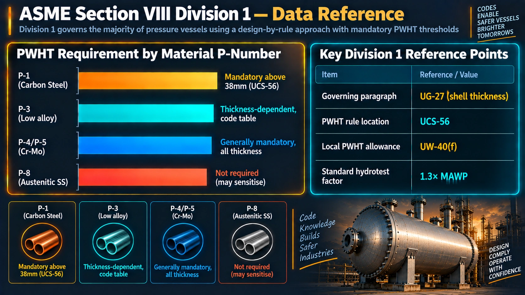
Post-weld heat treatment is performed to relieve residual stresses introduced during welding, improve toughness in the heat-affected zone, and reduce the risk of stress corrosion cracking and hydrogen-induced cracking in susceptible materials and environments. Division 1 specifies PWHT requirements by material P-Number in UCS-56 and UCS-56.1 for carbon and low-alloy steels.
PWHT Requirements for P-1 Carbon Steel (UCS-56)
Post-weld heat treatment is mandatory for P-1 carbon steel weld joints when any of the following conditions apply:
- Nominal thickness at any weld joint exceeds 1.5 in. (38 mm) for most P-1 materials (reduced to 1.25 in. / 32 mm for some specifications)
- Any thickness, when the design temperature is below −29°C (−20°F) and impact testing is required
- Any thickness, when the vessel is in lethal service per UW-2(a)
- Any thickness, when the material is a P-1 steel in hydrogen service that requires NACE compliance
PWHT Requirements for Alloy Steels (P-4, P-5)
For chromium-molybdenum steels (P-4 and P-5), PWHT is generally mandatory regardless of thickness, as these materials require controlled tempering to restore toughness and resist stress corrosion cracking in hydrogen and amine service. Key parameters for P91 (9Cr-1Mo-V) and P22 (2.25Cr-1Mo) PWHT:
| Material (P-Number) | PWHT Temperature Range | Minimum Hold Time | Max Heating / Cooling Rate |
|---|---|---|---|
| P-1 Carbon Steel | 595°C – 650°C (1,100°F – 1,200°F) | 1 hr/in. (25 mm) thickness; 1 hr minimum | 220°C/hr (400°F/hr) max above 315°C |
| P-4 (1.25Cr-0.5Mo) | 620°C – 705°C (1,150°F – 1,300°F) | 1 hr/in.; 2 hr minimum | 220°C/hr max above 425°C |
| P-5A (2.25Cr-1Mo / SA-387 Gr 22) | 650°C – 705°C (1,200°F – 1,300°F) | 1 hr/in.; 2 hr minimum | 55°C/hr (100°F/hr) max above 425°C |
| P-5B (9Cr-1Mo-V / P91) | 730°C – 790°C (1,350°F – 1,450°F) | 1 hr/in.; 2 hr minimum; with strict temperature uniformity ±14°C | Controlled ramp per WPS |
| P-8 Austenitic SS | Solution anneal: 1,040°C – 1,120°C (not PWHT in the conventional sense) | Rapid quench required | Not applicable — per UHA rules |
Local PWHT
Where it is impractical to heat treat the entire vessel (typically for large field-erected vessels), Division 1 permits local PWHT of individual weld joints in accordance with UW-40(f). Local PWHT requires that a circumferential band around the weld be uniformly heated to the specified temperature, with the band width extending at least one pipe or shell diameter from the weld centreline on each side, and that adequate insulation be applied to minimise the thermal gradient and prevent distortion. Thermocouple calibration and temperature recording are mandatory.
Pressure Testing — Hydrostatic and Pneumatic
Every pressure vessel fabricated under Division 1 must be subjected to a pressure test before it is placed in service. The pressure test verifies the structural integrity of the vessel and all its weld joints under conditions more severe than normal operating pressure, and reveals any gross leaks through weld defects or improper assembly. The test is performed in the presence of the Authorized Inspector, who must witness the test and confirm that it meets the code requirements before countersigning the nameplate and the Form U-1 data report.
Hydrostatic Test (UG-99)
The standard pressure test for internally pressurised vessels is the hydrostatic test, using water or another suitable non-hazardous liquid. The minimum hydrostatic test pressure is:
Pneumatic Test (UG-100)
A pneumatic test using compressed gas (typically air or nitrogen) at 1.1 × MAWP may be used where hydrostatic testing is impractical — for example, where the vessel cannot support the weight of water, where water contamination cannot be tolerated, or where the process fluid would be adversely affected by residual moisture. However, pneumatic testing carries a significantly higher energy release hazard than hydrostatic testing in the event of a failure (compressed gas stores far more energy per unit volume than an equal volume of liquid at the same pressure). Division 1 therefore requires that pneumatic tests be performed with additional safety precautions: a pre-test inspection at 50% of test pressure, and the presence of a trained safety observer. Many jurisdictions restrict or prohibit pneumatic testing of vessels above a defined volume-pressure product.
U-Stamp, Data Reports, and the Authorized Inspector
The ASME U-Stamp
The ASME U-stamp (or UV-stamp for pressure relief devices) is the certification mark applied to the nameplate of a pressure vessel that has been designed, fabricated, inspected, and tested in accordance with ASME Section VIII Division 1. The stamp may only be applied by a manufacturer holding a valid ASME Certificate of Authorization for the U-stamp, issued by ASME following a joint review by ASME and the Authorized Inspection Agency. The certificate must be renewed every three years through a periodic audit of the manufacturer’s Quality Control System.
The Authorized Inspector (AI)
The Authorized Inspector is an inspector employed by or contracted through an ASME-accredited Authorized Inspection Agency (AIA). AIAs are typically insurance companies or state inspection agencies that have been accredited by ASME and the National Board of Boiler and Pressure Vessel Inspectors. The AI’s role is to verify independent of the manufacturer that:
- All materials are properly certified and identified per the code
- Welding is performed in accordance with qualified WPS per Section IX
- All required NDE is performed, documented, and acceptable
- PWHT, where required, was performed and temperature-recorded to the code requirements
- The pressure test was performed at the correct pressure and met the acceptance criteria
- The nameplate content is correct and the vessel data are accurately reflected in the Form U-1
The AI must countersign the Form U-1 Manufacturer’s Data Report before the U-stamp is applied. The AI does not relieve the manufacturer of responsibility for code compliance — the manufacturer remains fully responsible for the quality and correctness of all work performed.
Manufacturer’s Data Report — Form U-1
The Form U-1 is the principal certification document for a Division 1 vessel. It records: vessel identification data (serial number, MAWP, design temperature, MDMT, shell dimensions, head type), material specifications for all pressure-containing parts, weld joint category and efficiency, NDE performed, PWHT details (temperature, hold time, chart number), pressure test pressure and medium, corrosion allowance, and the signatures of both the manufacturer’s authorised representative and the Authorized Inspector. The completed Form U-1 is filed with the National Board and a copy is retained by the owner for the life of the vessel.
Division 1 vs Division 2 vs Division 3
| Attribute | Division 1 | Division 2 | Division 3 |
|---|---|---|---|
| Design approach | Design-by-rules; explicit formulae | Design-by-analysis; detailed stress analysis required | Fracture mechanics and fatigue analysis; intensive |
| Safety factor (tensile strength) | 3.5 | 2.4 | Case-specific; lower than Div 2 |
| Allowable stress | Lower (≈ UTS/3.5) | Higher (≈ UTS/2.4); thinner walls possible | Higher; account for fatigue life explicitly |
| Pressure range | 15 psi – no upper limit (practical limit ≈3,000 psi for economy) | No lower limit; preferred above 3,000 psi for weight savings | Generally above 10,000 psi (ultra-high pressure) |
| NDE requirements | Based on selected joint efficiency (E = 0.70 to 1.0) | Full volumetric NDE mandatory for all pressure welds | Extensive NDE including UT of all welds; leak testing |
| Fatigue evaluation | Not required for most vessels (Appendix 5 voluntary) | Required for vessels subject to cyclic loading | Mandatory for all vessels |
| Weld quality requirements | Joint type dependent; fillet welds permitted | Full penetration butt welds only for pressure joints | Full penetration; additional qualification required |
| Documentation burden | Moderate — standard Form U-1 | High — detailed design analysis reports | Very high — fracture mechanics documentation |
| Typical application | General industrial vessels; most refinery and process equipment | High-pressure reactors, large storage vessels where weight matters | Autoclave equipment, CNG storage, ultra-high-pressure reactors |
| Certification mark | U-stamp | U2-stamp | U3-stamp |
Recommended References
Disclosure: WeldFabWorld participates in the Amazon Associates programme (StoreID: neha0fe8-21). If you purchase through these links, we may earn a small commission at no extra cost to you. This helps support free technical content on this site.
Frequently Asked Questions
What is the scope of ASME Section VIII Division 1?
ASME Section VIII Division 1 covers the design, fabrication, inspection, and certification of pressure vessels operating at internal or external pressures above 15 psi (103 kPa). It applies to vessels in the petrochemical, power, industrial gas, and process industries. Excluded are vessels covered by other ASME Sections (such as boilers under Section I), vessels with design pressure at or below 15 psi, and vessels with inside diameter not exceeding 6 inches at any pressure.
What is MAWP in ASME Section VIII Division 1?
Maximum Allowable Working Pressure (MAWP) is the maximum gauge pressure permissible at the top of a completed vessel in its operating position at a designated temperature. MAWP is determined by the weakest element of the vessel at the design temperature, calculated using the allowable stress values from ASME Section II Part D and the applicable design formulae in Section VIII Division 1. The MAWP is marked on the vessel nameplate and must never be exceeded in service.
What are the weld joint categories in ASME Section VIII Division 1?
ASME Section VIII Division 1 defines four weld joint categories per UW-3. Category A covers longitudinal and spiral welds in shells, nozzles, and communicating chambers. Category B covers circumferential welds in shells, nozzles, and communicating chambers. Category C covers welds connecting flanges, Van Stone laps, or tube sheets to shells or nozzles. Category D covers welds connecting nozzles or communicating chambers to main shells, heads, or side plates. The category determines the minimum required joint efficiency and the applicable NDE requirements.
What is MDMT in pressure vessel design?
Minimum Design Metal Temperature (MDMT) is the lowest permissible metal temperature at which a pressure vessel may be subjected to full design pressure. It is determined by the material toughness (Charpy impact data) and the vessel’s governing thickness, using the UCS-66 impact test exemption curves in ASME Section VIII Div 1. Vessels operating below their stamped MDMT at design pressure are at risk of brittle fracture. The MDMT is stamped on the vessel nameplate and must be referenced whenever the vessel is operated in cold weather or during upset conditions.
What NDE methods are required by ASME Section VIII Division 1?
ASME Section VIII Division 1 requires radiographic examination (RT) or ultrasonic examination (UT) of weld joints based on the joint type and the selected joint efficiency. Full RT (100%) is required for joint efficiency E = 1.0; spot RT (10%) allows E = 0.85; no RT permits E = 0.70. Full RT is mandatory regardless of design choice for lethal service vessels, unfired steam boilers above 50 psi, and vessels exceeding specific plate thickness thresholds. Liquid penetrant (PT) is required for austenitic stainless and non-ferrous welds. Magnetic particle (MT) is required for P-4 and P-5 alloy steel welds. Hardness testing is required after PWHT for alloy steels.
What is the difference between ASME Section VIII Division 1, Division 2, and Division 3?
Division 1 uses design-by-rules with a conservative safety factor of 3.5 on tensile strength and is the most widely used approach for general industrial pressure vessels. Division 2 uses design-by-analysis with a lower safety factor of 2.4 on tensile strength, requires more rigorous stress analysis including fatigue evaluation for cyclic service, and permits higher design stresses — resulting in thinner walls for high-pressure, large-diameter vessels where the engineering cost is justified. Division 3 covers ultra-high-pressure vessels (generally above 10,000 psi) and uses fracture mechanics and explicit fatigue analysis to qualify the design.
What is the role of the Authorized Inspector in ASME Section VIII fabrication?
The Authorized Inspector (AI) is an inspector employed by or contracted through an ASME-accredited Authorized Inspection Agency (AIA). The AI independently verifies that all materials, design, fabrication, NDE, testing, and documentation comply with ASME Section VIII Division 1. The AI witnesses the hydrostatic (or pneumatic) pressure test, reviews and countersigns the Manufacturer’s Data Report (Form U-1), and must countersign the U-stamp nameplate before the vessel is released. The AI does not relieve the manufacturer of responsibility — the manufacturer remains fully accountable for code compliance.
What is the hydrostatic test pressure requirement under ASME Section VIII Division 1?
For internally pressurised vessels, the minimum hydrostatic test pressure is 1.3 times the MAWP multiplied by the ratio of the allowable stress at test temperature to the allowable stress at design temperature (UG-99(b)). For example, a vessel with MAWP of 1.5 MPa designed for 250°C service would be hydrotested at a minimum of 1.95 MPa at ambient temperature if the allowable stress does not change between test and design temperature. The pneumatic test alternative (UG-100) uses 1.1 × MAWP but requires additional safety precautions due to the stored energy hazard of compressed gas.