Orbital Welding — Principles, Applications & Qualification
Orbital welding is an automated Gas Tungsten Arc Welding (GTAW / TIG) process in which the tungsten electrode rotates 360 degrees around a fixed tube or pipe joint, producing a continuous, fully fused circumferential weld without interruption. First developed in the early 1960s to meet the stringent quality demands of aircraft hydraulic tubing, orbital welding is today the industry benchmark for high-purity and high-integrity tube joints in pharmaceutical bioreactors, semiconductor ultra-pure gas distribution systems, nuclear steam generators, and offshore heat exchangers. By removing the manual positional skill variability of hand TIG welding, the process delivers welds that are consistent, traceable, and reproducible across entire production runs of hundreds or thousands of joints.
Unlike conventional mechanised welding where the workpiece rotates under a fixed torch, orbital welding holds the workpiece stationary. The weld head clamps around the tube joint and carries the electrode around it — hence the term “orbital.” This characteristic makes the process particularly suited to long pipe runs, confined spaces, cleanroom environments, and multi-joint assemblies where rotating the workpiece is impractical or impossible. When coupled with a well-developed weld schedule and a verified purge gas system, orbital GTAW routinely produces welds that pass 100 % radiographic and borescopic examination as standard production output rather than the exception.
This guide covers the complete technical picture: the physics of the orbital arc, closed-body versus open-body weld head selection, the structure of a weld schedule and how to develop one, shielding and purging best practice, qualification under ASME Section IX and AWS D18.1, common defect mechanisms and their remedies, and the industry applications that make orbital welding commercially indispensable.
How Orbital GTAW Works
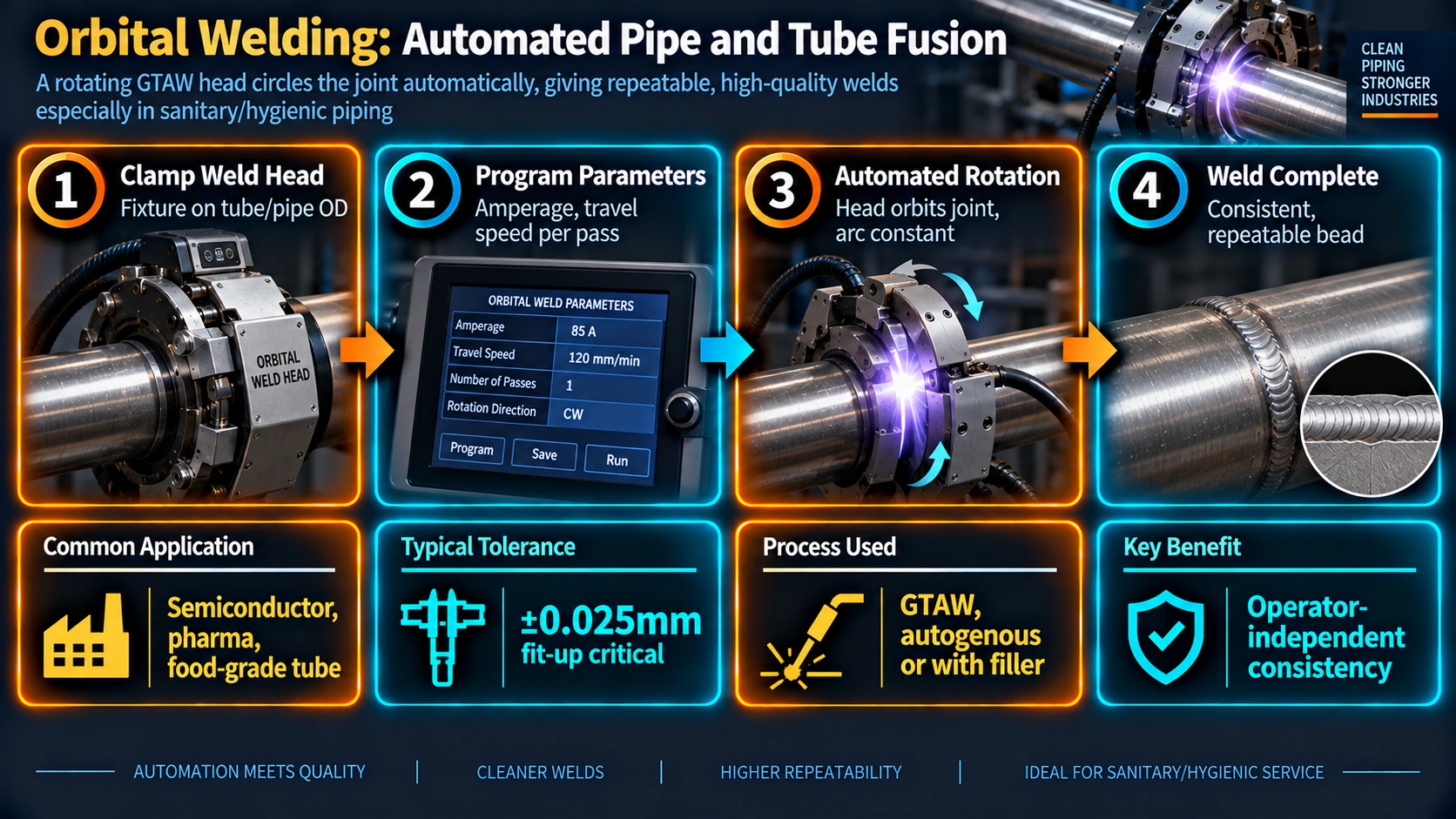
The orbital welding system comprises three integrated components: the power supply and controller, the weld head, and the gas supply system. The power supply generates DCEN (Direct Current Electrode Negative) welding current and drives the weld head rotor motor through a precision gearbox. The controller stores pre-programmed weld schedules and executes them automatically, adjusting current, travel speed, pulse frequency, and arc voltage on a sector-by-sector basis as the electrode progresses around the joint. Modern systems log all weld parameters in real time to an internal or external data system, creating a traceable electronic weld record for every joint — a key requirement in pharmaceutical and nuclear fabrication.
The Orbital Arc
Like conventional GTAW, the orbital process relies on a non-consumable tungsten electrode to strike and sustain a plasma arc between the electrode tip and the base material. The arc energy melts the adjacent tube wall to form a weld pool. Because the electrode moves around the tube at a constant programmed travel speed, the joint passes through four distinct positional orientations during a single revolution: flat at 12 o'clock, vertical-down at 3 o'clock, overhead at 6 o'clock, and vertical-up at 9 o'clock. The effective heat input required and the behaviour of the molten pool under gravity differ substantially at each position, which is why sector-specific parameter programming is essential to producing a uniform, fully penetrated weld around the full circumference.
In autogenous (no filler wire) orbital welding — the dominant mode for thin-wall tubing up to approximately 3.0 mm wall — the weld schedule manages this variation by modulating welding current and travel speed through programmable sectors. The 12 o'clock flat position requires the highest current to achieve adequate penetration; the 6 o'clock overhead position requires the lowest current because the molten pool tends to sag under gravity and because cumulative heat in the tube wall by the midpoint of the rotation is greatest, reducing the energy required to sustain the pool.
Pulsed Current Operation
Most modern orbital power supplies operate in a pulsed mode, alternating between a high “peak” current (Ip) and a lower “background” current (Ib) at a programmed pulse frequency — typically 0.5–5 Hz for pool-control pulsing. Pulsing reduces average heat input, controls weld pool size, and improves penetration consistency by allowing the pool to partially solidify between pulses before the next energy peak re-melts and drives it deeper into the joint. The duty cycle — the fraction of each pulse period spent at peak current — is independently programmable for each sector, giving the schedule developer fine control over the energy delivered to each positional zone without needing abrupt step changes in travel speed that could destabilise the arc.
Orbital Weld Head Types
Closed-Body (Enclosed) Weld Heads
Closed-body weld heads enclose the entire joint area within an inert-gas-purged rotor chamber. The tungsten electrode rotates inside the sealed housing, which is continuously flooded with argon. This design provides excellent atmospheric exclusion that is essential for inside-bore oxidation control in sanitary and high-purity tubing, consistent arc-to-work distance because it is fixed by the rotor geometry, and clean, borescope-inspectable welds with minimal heat tint when purge gas quality is maintained. Closed-body heads are generally limited to tube ODs from approximately 1.6 mm up to 168 mm, produce autogenous welds only (no filler wire feed), and are the standard choice for pharmaceutical, biotech, semiconductor, and food-grade piping systems.
Open-Body (Open-Arc) Weld Heads
Open-body weld heads carry the torch on a rotating ring or carriage that clamps around the pipe outside diameter. The arc is exposed to the atmosphere, so external gas trailing shields and a separate back-purge system must be employed. Open heads accept cold or hot wire filler addition, larger pipe diameters with no practical upper limit, thicker walls requiring multi-pass schedules, and arc voltage control (AVC) with oscillation for bevel-groove joint welding. They are widely used in power plant boiler tubing, offshore pipeline spools, and nuclear component fabrication where wall thickness and filler requirements make the closed-body approach impractical.
| Feature | Closed-Body Head | Open-Body Head |
|---|---|---|
| Diameter range | 1.6 mm – 168 mm OD | 50 mm OD – unlimited |
| Wall thickness range | Typically < 3 mm (autogenous) | Up to 40+ mm (multi-pass) |
| Filler wire capability | No | Yes (cold or hot wire) |
| Shielding method | Integral sealed gas chamber | External trailing shield + purge dam |
| Typical application | Pharma, semiconductor, food, biotech | Power plant, offshore, nuclear, refinery |
| Arc visibility during welding | Not visible — relies on data monitoring | Visible via integrated camera system |
| Arc voltage control (AVC) | Not typical | Standard feature |
| Oscillation capability | Not available | Available — used for bevel welds |
| Inside bore heat tint control | Excellent (enclosed integral purge) | Good (external trailing shield + separate purge) |
Programming a Weld Schedule
The weld schedule is the heart of the orbital process — the equivalent of a manual welder's positional skill, codified into a set of numerical parameters stored in the power supply controller. Developing a robust schedule requires systematic understanding of how key variables interact and how they must change around each positional zone of the 360-degree rotation.
Schedule Structure
A standard orbital weld schedule is divided into a number of levels or sectors, each defining a portion of the rotation. Common arrangements are 2-, 4-, or 8-level schedules. A 4-level schedule assigns approximately 90 degrees to each quadrant, though sector boundaries and widths can be adjusted independently. For each sector, the schedule independently specifies:
- Peak current (Ip) — primary melting energy during the high-current pulse phase
- Background current (Ib) — sustaining energy between pulses; prevents arc extinction
- Pulse frequency (Hz) — rate of Ip / Ib cycling
- Duty cycle (%) — fraction of each pulse period spent at Ip
- Travel speed (RPM or mm/min) — electrode rotation rate through the sector
- Shield / purge gas flow rate (L/min)
Heat Input Calculation for Orbital GTAW
Heat input for orbital GTAW is calculated using the average welding current (accounting for pulsed duty cycle) and the programmed travel speed. The formula is applied sector by sector, and all values across the schedule must fall within the heat input range established by the PQR:
This deliberate reduction from 0.693 to 0.380 kJ/mm at 6 o'clock prevents sagging of the weld pool under gravity and maintains a consistently penetrated, slightly convex internal bead profile around the full circumference. The Sector 1 to Sector 3 peak current ratio typically falls between 1.3:1 and 1.6:1 for thin-wall austenitic stainless tubing but must always be confirmed by weld trials and four-quadrant cross-section examination for every diameter-wall combination.
Schedule Development Step-by-Step
- Start from the machine manufacturer's baseline schedule for the tube OD and nominal wall thickness.
- Run autogenous test welds on coupon tube pairs of the same heat, lot, and specification as production material.
- Visually inspect the outside surface for uniform bead width, and the inside bore by borescope for heat tint colour and penetration profile.
- Section the weld at 12, 3, 6, and 9 o'clock. Prepare, mount, and etch metallographic cross-sections.
- Examine for complete ID penetration, consistent fusion zone width, HAZ extent, and absence of porosity or lack-of-fusion at each quadrant.
- Adjust sector parameters iteratively and re-weld until all four positions meet visual and macro acceptance criteria.
- Lock the finalised schedule as a read-only record. Run three consecutive qualification welds under production conditions to confirm repeatability before releasing to production use.
Shielding Gases and Purging
Shield Gas Selection
Pure argon (99.999% purity, Grade 5.0) is the standard shielding gas for orbital GTAW on austenitic stainless steels, duplex stainless steels, and nickel alloys. Argon provides excellent arc stability at the low current levels typical of thin-wall tubing, and its density (greater than air) helps it blanket the weld zone inside the closed-body head chamber effectively. Helium additions (typically 5–30% He, balance Ar) are used when wall thickness exceeds approximately 3 mm and greater penetration is required, when the material has high thermal conductivity (copper alloys, aluminium), or when travel speed must be increased without sacrificing penetration depth.
Back Purging
Achieving an oxidation-free inside bore surface is a fundamental quality requirement for orbital GTAW of stainless tubing, particularly in pharmaceutical applications where inside bore cleanliness is regulated under FDA cGMP and ASME BPE. Purging displaces atmospheric oxygen from the tube bore on both sides of the joint with inert gas before and throughout the weld cycle.
Purge Procedure
- Install gas-tight purge dams or plugs at each end of the tube section. Inspect dam seals — leaking dams are a primary cause of purge failure and inside bore oxidation.
- Connect 99.999% Ar purge supply to one end and allow gas to flow until O2 concentration at the exit falls below 20 ppm, measured with a calibrated trace-oxygen analyser.
- For pharmaceutical BPE-grade work, purge to below 10 ppm O2 before striking the arc. For semiconductor UHP systems, below 1 ppm is required.
- Maintain purge flow throughout welding and until the weld and HAZ cool below approximately 200°C to prevent post-weld oxidation of chromium-sensitised metal.
- Control purge gas flow rate so bore velocity does not disturb the weld pool. Typical rates for small-bore tubing are 2–10 L/min depending on bore cross-sectional area.
Heat Tint Assessment
After welding, the inside bore is assessed for heat tint (oxidation colour) against the AWS D18.1 colour chart. Class I welds require a silver or very light gold inside bore colour. Heat tint progresses through straw, gold, brown, blue, and grey as oxidation severity increases. Grey heat tint indicates severe chromium depletion of the passive oxide layer, compromising corrosion resistance, and is a mandatory rejection criterion requiring weld removal and re-welding. The outside weld surface is assessed similarly, with some construction codes permitting slightly more heat tint on the OD than on the critical ID contact surface.
Compatible Materials and Size Ranges
Orbital GTAW is applicable to the full range of materials weldable by conventional GTAW. It is most extensively used on austenitic stainless steels (316L and 304L) but is equally well established on duplex stainless, nickel alloys, titanium, and low-alloy steels. Special heat input constraints apply to duplex stainless, P91, and titanium, all of which require precise schedule control to maintain required microstructure.
| Material | P-Number (ASME IX) | Typical Application | Special Considerations |
|---|---|---|---|
| 304L / 316L Stainless | P-8 | Pharma, food, biotech, semiconductor | L-grade; sensitisation not a service concern |
| Duplex SS 2205 | P-10H | Offshore, desalination | N2 in purge; verify delta ferrite |
| Super-Duplex 2507 | P-10H | Subsea, aggressive chloride | Tight heat input limits; check PREN |
| Inconel 625 / 825 | P-43 / P-45 | CPI, offshore, nuclear | Higher arc voltage; Ar-He for penetration |
| Hastelloy C-276 | P-43 | Aggressive chemical process service | Low heat input; rapid solidification critical |
| Titanium Grade 2 | P-51 | Aerospace, medical, desalination | Full trailing shield; purge <50 ppm O2 |
| Carbon / Low-Alloy Steel | P-1 / P-4 | Power plant, general industry | Preheat per CE calculation; filler required |
| P91 (9Cr-1Mo-V) | P-5B | High-temperature power plant piping | Preheat 200°C+; PWHT mandatory; hardness <250 HV |
Industry Applications
Pharmaceutical and Biotech
This is the largest single application sector for closed-body orbital welding. Pharmaceutical water-for-injection (WFI) systems, clean steam distribution, bioreactor process piping, and CIP/SIP loop tubing are built almost exclusively with orbital GTAW in compliance with ASME BPE and FDA cGMP regulations. Inside bore welds must be free from crevices, pits, and surface irregularities where microbial biofilm could accumulate. Inside surface roughness is specified at Ra 0.51 μm maximum for electropolished surfaces, and heat tint must not exceed Class I per AWS D18.1. The repeatability and parameter traceability of orbital welding are essential for IQ/OQ/PQ regulatory validation documentation required by global drug regulatory agencies.
Semiconductor and Electronics Fabrication
Ultra-high-purity (UHP) gas distribution systems in semiconductor fabrication facilities carry process gases at purities measured in parts per trillion. Any surface discontinuity at a weld — a crevice, pit, or rough bead — can adsorb gas molecules that later desorb into the process stream and contaminate product wafers. Orbital welding of electropolished-grade 316L stainless tubing (Ra < 0.25 μm) is mandatory. Purge and shield gas oxygen content must be maintained below 1 ppm, verified by calibrated trace-oxygen analysers and certified with each cylinder delivery.
Power Generation
Open-body orbital systems are used extensively in nuclear steam generator tube replacement, heat exchanger tube-to-header welds, boiler tube fabrication, and high-energy pipe spool assembly. In nuclear applications, orbital welding provides the dimensional consistency and weld traceability demanded by 10 CFR 50 Appendix B quality assurance programmes and ASME Section III. Orbital hot-wire GTAW root passes are used on large-bore reactor coolant system piping in pressurised water reactor plants worldwide. For conventional power plant boiler tube banks, the productivity advantage of orbital over manual TIG — particularly in congested multi-row header assemblies — is commercially significant.
Aerospace and Defence
Hydraulic tubing (titanium and stainless), fuel system lines, and actuator bodies in commercial and military aircraft are produced with orbital GTAW to meet MIL-STD and AMS specifications. Thin walls (0.5–2.0 mm) and tight geometric tolerances of aircraft tubing are ideally suited to the autogenous closed-body process. Orbital welds in aerospace are typically subjected to 100% radiographic examination and helium leak testing at design pressure. The weld data log serves as a permanent manufacturing record for airworthiness certification.
Oil, Gas, and Petrochemical
Subsea umbilical tubes, wellhead flow lines, and heat exchanger bundles use orbital GTAW for butt welds in exotic alloys. The sour service environment dictates hardness limits (maximum 22 HRC per NACE MR0175/ISO 15156) that orbital welding's controlled heat input achieves more reliably than manual hand TIG. Consistent heat input also limits the chromium sensitisation and sigma-phase formation that reduce corrosion resistance in the HAZ of manually welded stainless and duplex alloys.
Qualification Requirements — ASME Section IX, AWS D18.1, ASME BPE
ASME Section IX
Orbital welding is a mechanised GTAW process fully subject to the procedural qualification requirements of ASME Section IX. A Welding Procedure Specification (WPS) and supporting Procedure Qualification Record (PQR) are mandatory for every P-Number group combination. The essential variables applicable to orbital GTAW include:
- Change in P-Number or Group Number of the base material (QW-403)
- Addition or deletion of filler metal; change in filler F-Number or A-Number (QW-404)
- Change in shielding gas type, composition, or flow rate beyond specified limits (QW-408)
- Change in heat input per QW-409 (increase beyond or decrease below PQR-qualified values)
- Change in welding position beyond those qualified (QW-405)
- Change in base metal thickness or tube diameter outside the qualified range (QW-451, QW-452)
- Change from pulsed to non-pulsed current (supplementary essential variable when Charpy impact testing is required by the construction code)
AWS D18.1 — Sanitary Applications
AWS D18.1 (Specification for Welding of Austenitic Stainless Steel Tube and Pipe Systems in Sanitary Applications) provides qualification requirements specific to pharmaceutical, food, and beverage work and defines three weld classes:
| Class | Inside Bead Profile | Heat Tint Limit | Typical Application |
|---|---|---|---|
| Class I | Full penetration; slight underbead acceptable; no crevices or sharp notches | Silver to light gold only | WFI, clean steam, API drug manufacturing |
| Class II | Full penetration; slight crown acceptable; smooth transition | Up to brown acceptable | Purified water, clean process fluids |
| Class III | Full penetration; wider profile tolerance | Up to blue acceptable | General sanitary service, CIP loops |
ASME BPE
The ASME BPE (Bioprocessing Equipment) standard incorporates and extends AWS D18.1. BPE specifies weld acceptance by internal surface finish class (SF1 through SF6 for mechanically polished, electropolished, and as-welded surfaces), inside bore geometry tolerances, and the requirement that all inside weld surfaces be free from microbially retentive features. Production welds in BPE systems are inspected 100% by video borescope, with each inspection recorded and retained. The weld data log — schedule ID, verified O2 purge level, gas lot and purity certificate, weld date, and operator ID — is retained as part of the IQ/OQ/PQ validation documentation package.
Procedure Qualification Test Requirements
For orbital GTAW PQR development, test welds are subjected to: visual examination of the outside surface and inside bore by borescope; transverse tensile tests per QW-150; root and face guided bend tests per QW-160; macro-section examination at 12, 3, 6, and 9 o'clock; radiographic or ultrasonic examination where required by the construction code; ferrite number measurement for austenitic and duplex stainless welds; hardness survey for P-4, P-5, and sour-service materials; and Charpy impact testing per UG-84 if low-temperature service is specified by the construction code.
Defects, Causes, and Remedies
| Defect | Primary Cause | Corrective Action |
|---|---|---|
| Incomplete penetration at 6 o'clock | Sector 3 peak current too low; travel speed too high through overhead zone; fit-up gap too tight | Increase S3 peak current 5–8 A per trial; reduce S3 travel speed; verify fit-up gap and tube OD concentricity |
| Burn-through at 12 o'clock | Sector 1 peak current too high; wall thinner than nominal; S1 sector too wide angularly | Reduce S1 peak current; ultrasonically measure actual wall thickness; narrow S1 sector width |
| Internal oxidation / sugaring | Purge O2 above 20 ppm before arc start; purge flow interrupted; purge dam leaking; gas purity below Grade 5.0 | Purge longer until verified <20 ppm; inspect dam seals; check gas purity certificate; measure dew point |
| Tungsten inclusion | Electrode tip contacted the molten pool; current too high for electrode diameter; contaminated electrode | Reduce peak current; select larger electrode diameter; inspect and re-grind or replace electrode before welding |
| Subsurface porosity | Moisture in shield gas; oil, grease, or scale on tube surface; incorrect gas flow rate creating turbulence in chamber | Verify dew point; solvent-clean tube ends immediately before welding; set gas flow to manufacturer spec; check fittings for leaks |
| Misalignment / lateral offset | Non-square tube end faces; out-of-round tube OD; worn weld head clamp inserts | Face tube ends with orbital facing machine; verify OD roundness; inspect and replace worn clamp inserts |
| Variable bead width around circumference | Variable fit-up gap; inconsistent wall thickness; contaminated electrode; worn head bearings | Improve fit-up; use AVC if available; replace electrode; inspect weld head bearing for play |
| Heat tint beyond Class I on ID | Inadequate pre-weld purge; purge gas withdrawn too soon; excess heat input | Extend purge until verified <10 ppm O2; maintain purge until below 200°C; reduce schedule heat input |
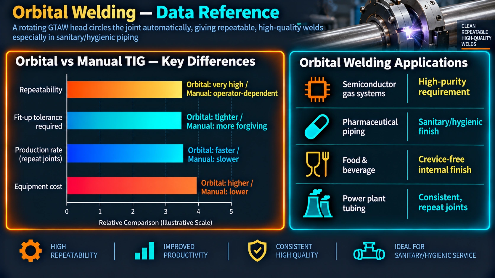
Orbital vs Manual GTAW — Technical Comparison
| Parameter | Orbital GTAW | Manual GTAW |
|---|---|---|
| Joint-to-joint consistency | Very High — schedule-controlled | Operator-dependent — skill and fatigue |
| Repeatability across shifts and sites | Identical within schedule tolerances; schedule is transferable | Varies; dependent on individual welder's qualification and day-to-day consistency |
| Deposition speed in volume production | Faster per joint once schedule is proven and head set up | Competitive for small batch or single one-off joints where set-up time dominates |
| Capital cost | High — power supply plus weld head(s) | Low — power supply, torch, and consumables only |
| Flexibility for non-standard geometry | Limited by weld head clamp geometry and rotor clearances | Unlimited — manual access to almost any joint configuration |
| Parameter documentation | Automated electronic data log per joint — schedule ID, current, speed, gas | Manual records only; relies on welder discipline and QC oversight |
| Regulatory validation capability | Ideal for IQ/OQ/PQ validation — pharma, nuclear, aerospace | Validated through WPQ records and in-process inspection programmes |
| Confined space capability | Good — compact weld head; no operator physical contact with joint | Requires physical welder access and adequate visibility; challenging in confined areas |
| Operator training requirement | Training on equipment set-up, schedule loading, and gas system management | Full GTAW positional welder qualification including all welding positions |
Recommended References
Disclosure: WeldFabWorld participates in the Amazon Associates programme (StoreID: neha0fe8-21). If you purchase through these links, we may earn a small commission at no extra cost to you. This helps support free technical content on this site.
Frequently Asked Questions
What is orbital welding?
Orbital welding is an automated GTAW (TIG) process in which the tungsten electrode rotates 360 degrees around a stationary tube or pipe joint. A weld head clamps around the joint and carries the electrode in a continuous orbital path, producing consistent, repeatable, fully penetrated welds without manual operator intervention on each pass. The workpiece remains fixed throughout the weld cycle, distinguishing orbital from conventional mechanised welding where the workpiece rotates.
What industries use orbital welding?
Orbital welding is used in pharmaceutical and biotech (high-purity stainless tubing for WFI and bioreactor systems), semiconductor fabrication (ultra-high-purity process gas lines), food and beverage processing, aerospace (hydraulic and fuel tubing), nuclear and conventional power generation, and offshore oil and gas where consistent, code-compliant, traceable welds are mandatory. It is the standard process for any application demanding high repeatability combined with regulatory documentation of individual joint quality.
Does orbital welding require a WPS and PQR under ASME Section IX?
Yes. Orbital welding is a mechanised GTAW process fully subject to ASME Section IX qualification requirements. A Welding Procedure Specification (WPS) and supporting Procedure Qualification Record (PQR) are mandatory. A Welder Performance Qualification (WPQ) is not required for the orbital machine operator since the weld is machine-controlled, but most construction codes that invoke Section IX require documented operator training on the specific orbital system. Check the applicable construction code and the owner's quality assurance manual for details.
What is the difference between a closed-body and open-body orbital weld head?
A closed-body weld head encases the joint in an inert-gas chamber, providing superior atmospheric shielding and inside bore surface quality for small-diameter tubing (1.6 mm to 168 mm OD) in high-purity applications. It produces autogenous (no filler wire) welds only. An open-body weld head mounts on a rotating ring around the pipe OD, accommodates filler wire addition and arc voltage control, accepts larger diameters without an upper limit, and is used for heavy-wall pipe fabrication in power plant, offshore, and nuclear applications.
What shielding gases are used in orbital GTAW?
Pure argon (99.999% purity, Grade 5.0) is the standard shielding and purge gas for stainless steel and nickel alloy orbital welds. Helium additions (5–30% He, balance Ar) are used to increase penetration on thicker walls or thermally conductive materials. For duplex stainless steels, nitrogen additions to the purge gas help maintain the ferrite-austenite balance. For semiconductor UHP applications, oxygen content in both shield and purge gas must be maintained below 1 ppm, verified by calibrated trace-oxygen analysers.
How is heat input controlled in orbital welding?
Heat input is controlled through the weld schedule stored in the power supply controller. The schedule divides the 360-degree rotation into sectors, each with independently programmable peak current, background current, duty cycle, travel speed, and pulse frequency. Amperage is tapered at the 6 o'clock position to compensate for heat accumulation in the tube wall. Heat input per sector is calculated as HI = (V × Iavg × 60) / (TS × 1,000) in kJ/mm, where Iavg accounts for the pulsed duty cycle. The peak current ratio between 12 o'clock and 6 o'clock typically falls between 1.3:1 and 1.6:1 for thin-wall austenitic stainless tubing.
Can orbital welding be qualified to AWS D18.1?
Yes. AWS D18.1 (Specification for Welding of Austenitic Stainless Steel Tube and Pipe Systems in Sanitary Applications) provides qualification requirements for orbital GTAW in pharmaceutical, food, and beverage applications. It defines three weld classes with progressively strict inside bore profile and heat tint acceptance criteria. Class I (silver to light gold heat tint only) is mandatory for WFI, clean steam, and API pharmaceutical manufacturing environments. ASME BPE extends these requirements with surface finish class designations and mandatory 100% borescope inspection of all production welds.
What common defects occur in orbital welds and how are they prevented?
Common defects include incomplete penetration at 6 o'clock (low Sector 3 current or high travel speed), internal oxidation or sugaring (purge O2 above 20 ppm), tungsten inclusions (electrode contact with the pool or excess current for electrode diameter), and geometric misalignment from poor tube-end preparation or worn weld head clamp inserts. Prevention requires verified purge gas purity below 20 ppm O2 before each arc start, correct electrode geometry and current levels matched to electrode diameter, systematic sector-by-sector schedule development validated by cross-section macro at all four clock positions, and consistent tube-end facing and solvent cleaning immediately before clamping.