ITP (Inspection & Test Plan) — How to Prepare
An Inspection and Test Plan (ITP) is one of the most important quality documents on any welding or fabrication project. It is the master schedule of every inspection, examination, and test activity that must take place during the manufacture of a component — from the moment materials arrive at the fabrication shop to the final pressure test and documentation review before dispatch. More than a checklist, an ITP defines exactly who must be present at each activity, on what authority, and what constitutes a passed result. It is the primary tool by which a client, third-party inspector, or regulatory authority exercises oversight of a fabricator's work without being physically present at every step of the process.
In the welding and pressure equipment sector, ITPs are required on virtually every project that involves a recognised code — ASME Section VIII Division 1, AWS D1.1, EN 13480, or ISO 15614 — or that involves a client or engineering procurement contractor (EPC) with a formal quality management system. An ITP that is poorly structured, incomplete, or misunderstood by the fabrication team leads directly to missed inspections, rework, disputes at final certification, and project delays. Getting the ITP right from the start of a project is not a bureaucratic exercise — it is a core engineering responsibility.
This guide covers everything you need to know to prepare a technically complete and contractually sound ITP: the definitions of Hold Points, Witness Points, Review Points, and Notifications; the required column structure; a step-by-step preparation process; a fully worked sample ITP for a pressure vessel fabrication project; a phase-by-phase checklist of typical inspection activities; applicable code references; and the most common mistakes made by fabricators and how to avoid them.
What Is an Inspection and Test Plan?
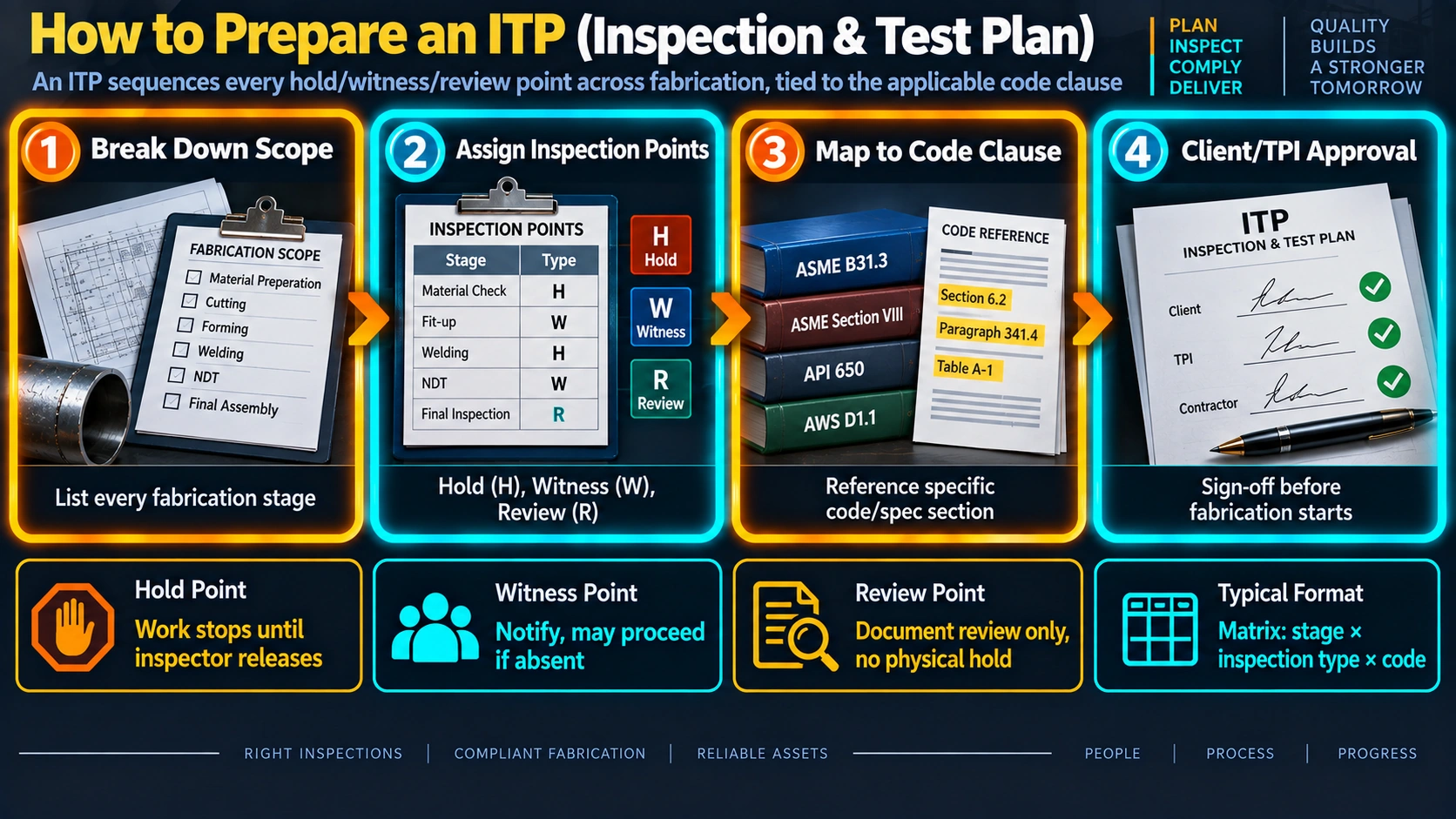
An ITP is a controlled quality document — typically a table — that lists every inspection, examination, and test activity required during the fabrication or construction of a specified scope of work. For each activity, the ITP identifies:
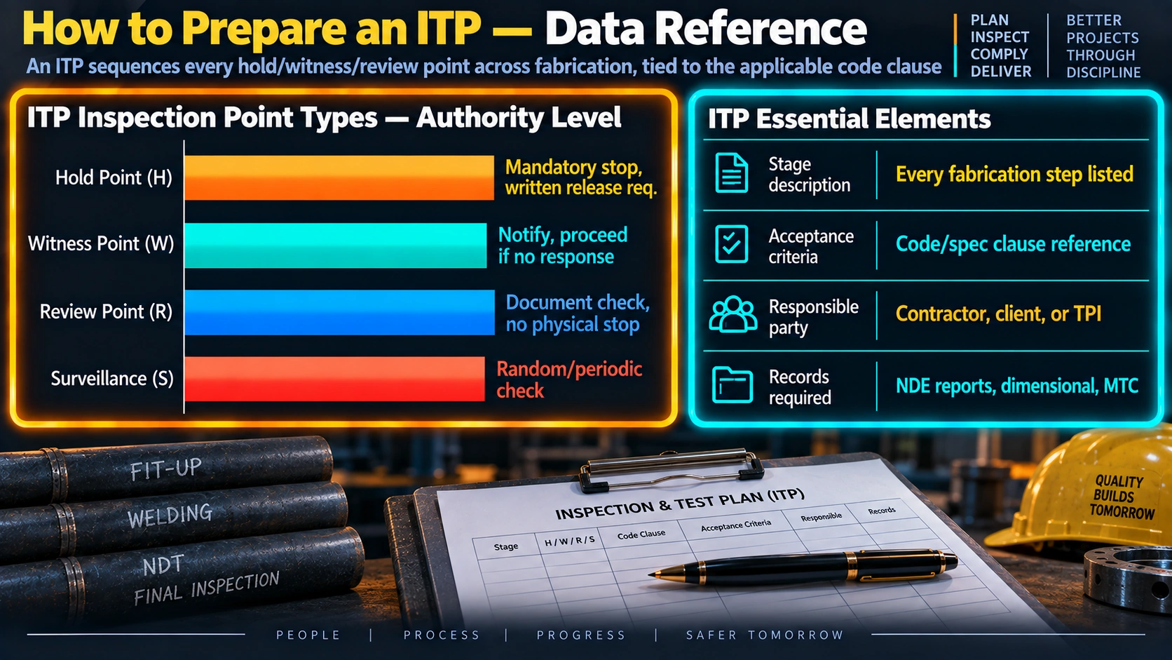
- The activity itself (what is being inspected or tested)
- The applicable code, standard, or specification that governs the activity
- The acceptance criteria (the pass/fail threshold)
- The responsible party (who performs the activity: fabricator, client, third-party inspector, regulatory authority)
- The inspection category for each party — Hold (H), Witness (W), Review (R), or Notification (N)
- The record or document that provides evidence of completion
The ITP is prepared by the fabricator's quality department and submitted to the client and/or the third-party inspection authority for review and approval before fabrication begins. Once approved, the ITP becomes a contractually binding document. No inspection activity may be omitted, downgraded in category, or modified without a formal revision agreed by all parties. Each line of the ITP is signed off by the applicable inspector when the activity is completed and accepted, and the signed ITP forms part of the permanent quality dossier (Material Dossier, Vendor Data Book, or Manufacturer's Record Book) delivered to the client at project completion.
Hold Points, Witness Points, Review Points, and Notifications
The inspection category assigned to each activity for each party is the most important and most often misunderstood element of an ITP. There are four standard categories, typically abbreviated H, W, R, and N (or S for “Surveillance” in some project specifications). Understanding the obligation each creates for the fabricator and the inspector is essential.
Hold Point (H)
A Hold Point is an absolute stop in the fabrication sequence. Work cannot proceed past a Hold Point under any circumstances until the designated party — the client, the third-party inspector, or the regulatory authority — has physically attended the activity, examined the work or records, found them acceptable, and formally signed the ITP line item. If the designated inspector fails to attend, work remains stopped until they do. There is no provision for the fabricator to proceed without the inspector's signature at a Hold Point, regardless of schedule pressure. Examples of mandatory Hold Points include the hydrostatic pressure test (for an Authorized Inspector under ASME Section VIII), final dimensional inspection, and first article weld approval.
Witness Point (W)
A Witness Point is an activity that the designated party intends to attend and witness. The fabricator must notify the inspector in advance (within the agreed notification period — typically 24 to 72 hours) that the activity is scheduled. If the inspector attends, they witness the activity, examine the result, and sign the ITP line item. If the inspector does not attend after the notification period has elapsed and the agreed notice has been given, the fabricator may proceed with the activity and it is considered satisfied for ITP purposes. The fabricator documents that the notification was given and the inspector elected not to attend. Witness Points are used for activities that the client considers important but not so critical that work must stop if the inspector has schedule conflicts.
Review Point (R)
A Review Point (also called a Document Review Point or sometimes Approval Point) is an activity where the designated party reviews and formally approves a document, record, or report rather than attending a physical activity at the fabrication shop. Examples include review and approval of weld maps, NDE reports, PWHT temperature recorder charts, material mill test reports, weld procedure registers, and dimensional inspection reports. The document must be reviewed and formally accepted (signed) before the next stage of fabrication proceeds. Review Points are less restrictive than Witness Points because they do not require physical presence, but they still create a mandatory sign-off obligation before work advances.
Notification (N)
A Notification (sometimes called S for Surveillance, or simply an information point) is the lowest obligation level. The fabricator notifies the inspector that an activity is scheduled, and the inspector may attend at their own discretion, but work is not delayed whether the inspector attends or not. Notifications are used for routine in-process activities that are conducted frequently and where the fabricator's own in-process quality records provide sufficient assurance without independent witness. Examples include routine welder identity checks on ongoing production welds and intermediate dimensional checks on repetitive parts.
ITP Document Structure — Required Columns
While ITP formats vary between clients, EPCs, and industries, the core columns are consistent across all applications. A technically complete ITP must contain at minimum the following columns:
| # | Column Name | Content | Notes |
|---|---|---|---|
| 1 | Item / Line No. | Sequential reference number for each inspection activity | Enables traceability and cross-referencing in the quality dossier |
| 2 | Fabrication Phase / Activity | Description of the inspection or test activity | Must be specific enough to identify exactly what is being checked |
| 3 | Reference Document | Code, standard, spec, or drawing that governs the activity | e.g. ASME VIII UG-99, AWS D1.1 Cl. 6, ISO 5817, Project Spec Rev 3 |
| 4 | Acceptance Criteria | Pass/fail threshold or reference to where it is defined | Must be objective and verifiable. Avoid vague terms like “to satisfaction of” |
| 5 | Fabricator (MFR) | Inspection category for the fabricator's own QC inspector | Fabricator is always H or W for their own activities — never N |
| 6 | Client (CL) | Inspection category for the client's site inspector or QC representative | H, W, R, or N depending on risk and contractual requirement |
| 7 | Third-Party Inspector (TPI) | Inspection category for the independent inspection authority or NDE contractor | H for code-mandatory inspections (e.g. AI for ASME hydro test) |
| 8 | Record / QC Document | The record that evidences completion: report number, form, certificate | e.g. NDE Report No., PWHT Chart No., Dimensional Checklist No. |
| 9 | Sign-off / Date | Signature and date of each inspector who performed or witnessed the activity | Columns for each party; blank until activity is completed and accepted |
| 10 | Remarks / NCR Ref. | Free text for deviations, NCR numbers, concession references | Critical for traceability if a non-conformance is raised against this activity |
Header Information
Every ITP must carry a document header block that identifies: the project name and number; the purchase order or contract number; the fabricator name and address; the client name; the item or tag number of the equipment being fabricated; the applicable code and edition; the ITP document number and revision; the date of issue; and the names and signatures of the fabricator's QC manager, the client's representative, and the TPI who approved the ITP before fabrication commenced. The revision history block must record every revision made to the ITP during the project, including the reason for the revision and the re-approval signatures.
Step-by-Step: How to Prepare an ITP
Sample ITP — Pressure Vessel Fabrication (ASME Section VIII Division 1)
The following sample ITP covers the principal fabrication activities for a carbon steel pressure vessel fabricated to ASME Section VIII Division 1 with full radiography (E = 1.0). Party abbreviations: MFR = Manufacturer/Fabricator, CL = Client Inspector, TPI = Third-Party Inspector (ASME Authorized Inspector for this scope).
| Item | Activity / Description | Reference | Acceptance Criteria | MFR | CL | TPI (AI) | Record |
|---|---|---|---|---|---|---|---|
| PHASE 1 — MATERIAL RECEIVING & IDENTIFICATION | |||||||
| 1.1 | Receive and verify plate MTRs against PO and ASME material spec | ASME II Part A; PO | Heat no., spec, grade, thickness, chem & mech properties per SA-516 Gr 70 | H | R | R | MTR File Ref. |
| 1.2 | Positive Material Identification (PMI) — XRF on all pressure-containing plate | Client Spec CS-007 Cl.4.2 | Alloy composition matches MTR within spectrometer tolerance | H | W | N | PMI Report |
| 1.3 | Material identification transfer — heat/lot no. marked on all cut pieces | ASME VIII UG-77, UG-93 | Each piece traceable to original heat. Low-stress stamp or paint mark only. | H | W | N | Material Traceability Log |
| PHASE 2 — JOINT PREPARATION & FIT-UP | |||||||
| 2.1 | Shell plate edge preparation inspection — bevel angle, root face, root gap | WPS Rev 4; ASME VIII UW-9 | Bevel per WPS (±2.5°); root face ±0.8 mm; cleanliness free from scale, oil | H | W | N | Fit-Up Inspection Report |
| 2.2 | Shell longitudinal seam fit-up inspection — alignment, offset, gap | ASME VIII UW-33; UW-35 | Misalignment (high-low) ≤ t/4 or 3/16 in. (4.8 mm) max; gap per WPS | H | W | N | Fit-Up Inspection Report |
| 2.3 | Welder & WPS identity verification at each weld joint prior to welding | ASME IX QW-301; WPQ on file | Welder stamp ID traceable to current WPQ. WPS applicable to joint, position, process. | H | N | N | Weld Map; WPQ File |
| PHASE 3 — WELDING | |||||||
| 3.1 | Pre-heat verification prior to welding — contact thermometer or thermocouple | WPS Rev 4; ASME IX QW-406; Project Spec Cl.5 | Preheat temperature ≥ minimum specified on WPS; verified within 75 mm of joint | H | W | N | Preheat Record Form QC-03 |
| 3.2 | First (root) pass visual inspection — longitudinal seam Cat A | ASME VIII UW-35; WPS | No cracks, no lack of fusion, complete root fusion before fill passes commence | H | W | N | In-Process Weld Report |
| 3.3 | Interpass temperature monitoring (P-4 and P-5 steels only) | WPS Rev 4; ASME IX QW-406.3 | Interpass temp ≤ maximum specified on WPS; measured immediately before next pass | H | N | N | Interpass Temp Log |
| 3.4 | Completed weld visual examination — all Category A and B joints | ASME VIII UW-35; UW-36 | No cracks, complete fusion, no undercut >1/32 in., no surface porosity > 3/8 in. dia. | H | W | W | Visual Exam Report VT-01 |
| PHASE 4 — NON-DESTRUCTIVE EXAMINATION | |||||||
| 4.1 | Radiographic examination (RT) — 100% of all Cat A and B butt welds | ASME VIII UW-11(a); ASME V Art. 2; ASME VIII UW-51 | No cracks, no incomplete penetration, no inclusions exceeding UW-51 limits | H | R | R | RT Report RT-[no.] |
| 4.2 | Magnetic particle testing (MT) — all completed nozzle attachment welds | ASME VIII Appendix 6; ASME V Art. 7 | No linear indications. Rounded indications per App. 6 acceptance criteria. | H | W | R | MT Report MT-[no.] |
| 4.3 | Review of all NDE reports and radiographs by Level III or ASME RT AI | ASME VIII UW-51; SNT-TC-1A | All radiographs interpreted and accepted by qualified Level II or Level III RT technician | H | R | H | NDE Acceptance Report |
| PHASE 5 — POST-WELD HEAT TREATMENT | |||||||
| 5.1 | PWHT furnace chart review — temperature, ramp rates, soak time, thermocouple locations | ASME VIII UCS-56; WPS PWHT Procedure Rev 2 | Temp range per UCS-56 Table; hold time ≥ 1 hr/in.; TC locations per procedure | H | R | H | PWHT Chart No. [chart no.] |
| 5.2 | Post-PWHT hardness survey — weld metal, HAZ, base metal adjacent to weld | ASME VIII UCS-56; NACE MR0175 (if sour) | Brinell hardness ≤ 200 HB (P-1 general); ≤ 22 HRC (NACE sour service) | H | W | W | Hardness Report HT-[no.] |
| PHASE 6 — DIMENSIONAL & FINAL INSPECTION | |||||||
| 6.1 | Final dimensional inspection — shell OD, length, out-of-roundness, nozzle orientation | ASME VIII UG-80; UG-81; Approved Drawing Rev 4 | OD tolerance per UG-80; nozzle orientation ±3 mm and ±1° per drawing | H | H | W | Dimensional Report DIM-01 |
| 6.2 | Nameplate content verification before stamping | ASME VIII UG-116; UG-119 | All nameplate data per UG-116: MAWP, MDMT, shell thickness, head thickness, design temp, NB No. | H | R | H | Nameplate Checklist |
| PHASE 7 — PRESSURE TEST | |||||||
| 7.1 | Hydrostatic pressure test — water; 1.3 × MAWP × (Stest/Sdesign) | ASME VIII UG-99(b) | No leaks, no distortion. Pressure held minimum 30 min. Gauge calibrated within 6 months. | H | H | H | Hydrostatic Test Report HT-01 |
| PHASE 8 — DOCUMENTATION & CERTIFICATION | |||||||
| 8.1 | Form U-1 Manufacturer's Data Report review and AI countersignature | ASME VIII UG-120; Mandatory Appendix W | All data fields complete and accurate; AI signature confirms code compliance | H | R | H | Form U-1 |
| 8.2 | Quality dossier (data book) review and acceptance before vessel dispatch | PO; Client Spec QR-002 | All ITP records present, signed, and traceable. No open NCRs. NB registration confirmed. | H | H | R | Data Book Acceptance Form |
Typical Inspection Activities by Fabrication Phase
The following is a reference checklist of inspection and test activities commonly included in ITPs for welded fabrication projects. Not all activities apply to every project — the applicable code, project scope, material type, and client specification determine which are mandatory.
Phase 1 — Material Receiving and Identification
- Mill Test Report (MTR) / Certificate of Conformance (CoC) verification against purchase order and applicable material standard
- Positive Material Identification (PMI) — XRF or OES spectrometry on alloy steel and stainless components
- Dimensional verification of incoming plate, pipe, fittings, flanges, and forgings
- Visual inspection for surface defects, laminations, and handling damage
- Material identification transfer and marking verification after cutting
- Impact test coupons verification (if low-temperature service; UCS-67)
- Ultrasonic examination of plate for laminations (if required by client spec or for pressure-retaining components ≥ specified thickness)
Phase 2 — Joint Preparation and Fit-Up
- Edge preparation inspection — bevel angle, root face, surface condition (free from scale, oil, moisture)
- Fit-up inspection — gap, alignment (high-low offset), root gap per WPS
- WPS and welder identity verification — confirm applicable WPS is displayed at the joint, welder's stamp ID verified
- Tack weld inspection (tack welds are considered part of the production weld under most codes)
- Purge gas installation and oxygen level verification (for stainless and high-alloy materials requiring back purging)
Phase 3 — Welding
- Pre-heat verification — temperature and extent (minimum 75 mm each side of joint) per WPS and applicable code
- Root pass visual inspection — before fill passes commence
- Back-gouging inspection (if double-sided joint) — visual and MT/PT to confirm sound metal before back-weld
- Interpass temperature monitoring (especially critical for P-4, P-5, and P-5B alloy steels)
- Filler metal identification check — confirm correct classification and lot number per WPS
- Completed weld visual examination — profile, surface condition, capping pass conformity
Phase 4 — Non-Destructive Examination
- Radiographic testing (RT) — full or spot per UW-11 and selected joint efficiency
- Ultrasonic testing (UT) — where RT is impractical or as a supplement (UW-53)
- Magnetic particle testing (MT) — nozzle welds, back-gouged surfaces, repair welds (P-4, P-5 materials)
- Liquid penetrant testing (PT) — austenitic stainless and non-ferrous welds (UHA-34)
- NDE report review and acceptance by Level II or Level III technician
- Weld repair scope review and re-examination after repair (re-NDE of repaired area)
Phase 5 — Post-Weld Heat Treatment
- PWHT procedure review before heat treatment commences
- Thermocouple placement and calibration verification
- PWHT temperature recorder chart review — all thermocouples in range, soak time met
- Post-PWHT hardness survey — weld metal, HAZ, and base metal
- Post-PWHT NDE (MT/PT where required — some codes require repeat NDE after PWHT for P-5B materials)
Phase 6 — Dimensional and Final Inspection
- Shell out-of-roundness check (UG-80)
- Head profile and knuckle radius check
- Nozzle position, orientation, and projection dimensional check against approved drawing
- Flange face finish and flatness verification
- Nameplate content verification before stamping (UG-116)
- Coating / painting inspection (DFT, holiday testing) if applicable
Phase 7 — Pressure Testing
- Hydrostatic test pressure calculation verification (1.3 × MAWP × stress ratio)
- Test gauge calibration verification (within 6 months)
- Hydrostatic test — pressure hold, inspection for leaks and distortion (UG-99)
- Pneumatic test (if applicable) — pre-test inspection at 50% test pressure (UG-100)
- Leak test of nozzle flanges and instrument connections
Phase 8 — Documentation and Certification
- Weld map completeness check — all welds identified, WPS and welder ID recorded
- NDE report index completeness — all welds covered, no gaps in coverage
- Form U-1 (or equivalent data report) review and AI countersignature
- National Board registration confirmation
- Quality dossier (data book) compilation, index review, and client acceptance sign-off
- U-stamp application and nameplate attachment verification
Code and Standard References in an ITP
Every ITP line item must cite the specific document, section, and clause that governs the activity. The following table lists the most commonly referenced standards in welding fabrication ITPs and the typical ITP activities they govern:
| Standard | Scope | Typical ITP Activities Governed |
|---|---|---|
| ASME Section IX | Welding, brazing, and fusing qualifications | WPS approval, WPQ verification, welder identity check at each joint, filler metal conformance |
| ASME Section VIII Div 1 | Pressure vessel design, fabrication, inspection | Fit-up, PWHT, RT scope, hydrostatic test pressure, nameplate content, Form U-1 |
| ASME Section V | NDE methods and procedures | RT, UT, MT, PT procedure qualification and execution; NDE technician qualification |
| ASME Section II Part D | Allowable stress values and material properties | MAWP calculation verification, hydrostatic test pressure ratio, PWHT temperature selection |
| AWS D1.1 | Structural steel welding code | Fit-up, joint geometry, preheat, NDE extent and acceptance criteria for structural welds |
| AWS D18.1 | Sanitary stainless tubing welding | Inside bore visual and borescope inspection, heat tint classification, Class I/II/III acceptance |
| ISO 3834 | Quality requirements for fusion welding of metallic materials | Overall welding quality system; review of welding-related quality activities and records |
| ISO 15614-1 | Welding procedure qualification — steels and nickel alloys | WPS and WPQR review, essential variable check, test results review |
| EN 13480 | European metallic industrial piping | Fit-up, NDE extent by weld category, PWHT, dimensional tolerances for piping systems |
| NACE MR0175 / ISO 15156 | Materials for H2S service | Hardness testing after PWHT, hardness acceptance limits, material certification review for sour service |
| SNT-TC-1A / ISO 9712 | NDE personnel qualification and certification | NDE technician qualification level verification before NDE activities commence |
| Project Specification | Client-specific additional requirements | PMI requirements, additional NDE scope, specific dimensional tolerances, paint inspection |
Notification Procedures and Notice Periods
The notification procedure — how and when the fabricator informs the client and TPI that a Witness Point or Hold Point activity is scheduled — must be defined in the ITP or in the associated Quality Plan before fabrication starts. Failure to follow the agreed notification procedure is itself a non-conformance, even if the subsequent inspection result is acceptable.
Common ITP Mistakes and How to Avoid Them
| Mistake | Consequence | How to Avoid |
|---|---|---|
| Fabrication starts before ITP is approved | No agreed inspection plan during early activities; retrospective sign-offs are not acceptable; may require re-inspection or re-work to satisfy the AI or client | Include ITP approval as a contract milestone with a fixed target date. No production welding begins before ITP is signed by all parties. |
| ITP activities listed out of fabrication sequence | Shop inspectors cannot follow the ITP in real time; Hold Points are missed; sign-offs happen out of order, reducing traceability | Walk through the actual fabrication sequence with the shop foreman before drafting the ITP. Map each ITP line to a specific production step in chronological order. |
| Vague or unmeasurable acceptance criteria | Disputes between fabricator and client inspector at inspection; subjective pass/fail decisions; delays to sign-off | Every acceptance criterion must reference a specific clause, table value, or drawing dimension. Eliminate phrases like “as per good practice” or “to the satisfaction of.” |
| Missing mandatory code Hold Points | Non-conformance against the applicable code; possible rejection of the component by the AI or regulatory authority; potential invalidation of U-stamp | Read the applicable code systematically before drafting the ITP. Cross-check against the code's own inspection summary clauses (e.g. ASME VIII UG-90 through UG-103). |
| No record identified for each ITP line item | Activities are performed but cannot be demonstrated to have been performed; objective evidence of conformance is missing from the quality dossier | Every ITP line must specify the exact record format or document type that will evidence completion. Pre-print or pre-number forms before fabrication begins. |
| ITP not revised when scope changes | ITP is no longer representative of the actual fabrication scope; inspection activities may be missed or duplicated; the signed ITP in the dossier does not match the actual work performed | Issue a formal ITP revision for every significant scope change. Obtain re-approval from all parties before the revised activities commence. Track revisions in the revision history block. |
| Witness Points treated as Hold Points by the client inspector | Programme delays when client inspector is unavailable; disputes over whether the fabricator had the right to proceed | Clearly define Witness Point and Hold Point obligations in the ITP header, agreed notice periods in writing, and the specific waiver procedure before fabrication commences. |
| NDE reports not linked to specific weld identities on the weld map | NDE coverage cannot be demonstrated for individual welds; gaps in coverage discovered at final dossier review require additional NDE or concession | Require that every NDE report references the specific weld joint number(s) from the approved weld map. Maintain a running NDE coverage index throughout fabrication. |
ITP and ISO 3834 Quality Requirements for Welding
ISO 3834 (Quality Requirements for Fusion Welding of Metallic Materials) is the international standard that defines the minimum quality management requirements for welding activities in fabrication. It does not specify inspection activities directly, but it mandates that the manufacturer establish and maintain a system of welding quality management that encompasses all activities from design and material control through to final inspection and documentation — precisely the scope that an ITP addresses.
ISO 3834 Part 2 (Comprehensive Quality Requirements) requires, among other things, that the manufacturer plan and document all inspection and testing activities, specify acceptance criteria, define the party responsible for each activity, and maintain records of all inspections and test results. The ITP is the industry-standard document used to satisfy these requirements in a format that is visible and auditable by the client, the certification body, and the construction code authority.
| ISO 3834-2 Requirement | How the ITP Satisfies It |
|---|---|
| Plan and document inspection and test activities for the complete welding scope | ITP lists every activity from material receiving through final pressure test in fabrication sequence |
| Specify acceptance criteria for each inspection and test activity | Acceptance criteria column references specific code clause, table value, or drawing dimension for every ITP line |
| Define responsible party for each activity | MFR, CL, TPI columns with H/W/R/N designations assign clear responsibility |
| Maintain records demonstrating that planned activities were performed | Record column specifies the exact quality record; sign-off column provides objective evidence of completion |
| Plan for the involvement of subcontractors (NDE, PWHT, test labs) | ITP identifies TPI activities and specifies the NDE report or PWHT chart as the deliverable record |
| Review and update quality plans when scope or specification changes | ITP revision control with re-approval requirement addresses scope changes formally |
Recommended References
Disclosure: WeldFabWorld participates in the Amazon Associates programme (StoreID: neha0fe8-21). If you purchase through these links, we may earn a small commission at no extra cost to you. This helps support free technical content on this site.
Frequently Asked Questions
What is an Inspection and Test Plan (ITP)?
An Inspection and Test Plan (ITP) is a quality document that identifies every inspection, examination, and test activity required during fabrication or construction of a component or system. For each activity it specifies the applicable code or standard, the acceptance criteria, the responsible party, and the level of involvement of the client, third-party inspector, and regulatory authority — classified as Hold Points (H), Witness Points (W), Review Points (R), or Notifications (N). The signed ITP forms part of the permanent quality dossier delivered to the client at project completion.
What is the difference between a Hold Point and a Witness Point in an ITP?
A Hold Point (H) is a mandatory stop in the fabrication sequence where work cannot proceed until the designated party has attended, inspected, and formally signed off. There is no provision to proceed without the inspector's signature regardless of schedule pressure. A Witness Point (W) is an activity that the designated party is notified to attend and intends to witness, but if they fail to attend after formal notification within the agreed notice period, the fabricator may proceed with work. Hold Points carry a higher level of quality assurance obligation and are used for safety-critical or code-mandatory inspections.
Who prepares the ITP?
The ITP is prepared by the manufacturer or fabricator's quality department and then reviewed and formally approved by the client and, where applicable, the third-party inspection authority or regulatory body. For ASME-coded vessels, the Authorized Inspector (AI) reviews the ITP to confirm that all mandatory code inspection activities are included. The approved and signed ITP becomes a contractually binding quality document. No fabrication activity covered by the ITP may commence before the ITP has been approved by all designated parties.
What activities are typically included in a welding fabrication ITP?
A welding fabrication ITP typically includes: material receiving and MTR/CoC verification, PMI (if required), dimensional inspection of incoming materials, joint preparation and fit-up inspection, welder and WPS identity verification at each joint, pre-heat verification, root pass and in-process weld inspection, NDE (RT, UT, MT, PT, VT) per the applicable code, PWHT temperature chart review and hardness testing, final dimensional inspection of the completed assembly, nameplate content verification, hydrostatic or pneumatic pressure testing, and quality dossier review and sign-off before dispatch.
What is a Review Point (R) in an ITP?
A Review Point (R) is an ITP activity where the designated party reviews and approves a document or record — such as a weld map, NDE report, PWHT chart, or material certificate — rather than physically attending the fabrication activity. The document must be reviewed and accepted before the next stage of fabrication proceeds. Review Points are less restrictive than Hold or Witness Points because they do not require physical attendance at the shop, but they still create a mandatory sign-off obligation that must be satisfied before work advances to the next phase.
How much advance notice is required for a Hold Point or Witness Point?
The required advance notification period is defined in the project quality plan or the ITP itself and agreed between the fabricator and the client before fabrication begins. Typical notification periods are 48 to 96 hours for Hold Points and 24 to 72 hours for Witness Points. For regulatory authority Hold Points such as the Authorized Inspector witnessing a hydrostatic test, the notice period may be specified by the applicable code or jurisdictional authority. Notification must always be made in writing — typically by email or formal Inspection Notification Form (INF) — verbal notification alone is not an acceptable record.
Is an ITP required by ASME Section VIII Division 1?
ASME Section VIII Division 1 does not use the term “ITP” explicitly, but it does require the fabricator to maintain a documented Quality Control System (QCS) that identifies all required inspection and test activities, responsible parties, and acceptance criteria. The ITP is the standard industry document used to satisfy this requirement. The Authorized Inspector reviews the ITP (or the equivalent quality plan) as part of the vessel certification process to confirm that all code-mandatory inspection activities are planned and controlled.
What codes and standards are referenced in a typical welding ITP?
A typical welding fabrication ITP references: ASME Section IX (welding procedure and welder qualification), ASME Section VIII Div 1 (pressure vessel design and inspection requirements), ASME Section V (NDE methods and procedures), AWS D1.1 or the applicable structural welding code, ISO 3834 (quality requirements for fusion welding), applicable material standards from ASME Section II or ASTM, NACE MR0175/ISO 15156 (for sour service hardness requirements), SNT-TC-1A or ISO 9712 (NDE personnel qualification), and the client's project specification for any requirements beyond the code minimum.
Related reading: How to Identify Metal: 10 Field Tests Every Welder Should Know