Pressure Vessel Fabrication & Types: Complete Engineering Guide
Pressure vessels are among the most safety-critical items of equipment in any processing plant. A pressure vessel is a closed container engineered to safely hold fluids or gases at pressures substantially different from the ambient environment — whether under internal pressure or external vacuum. From the compact air receiver in a compressor house to a 3,000-tonne spherical LPG storage sphere, every pressure vessel must be fabricated to a strict sequence of controlled operations governed by internationally recognised codes. This guide covers the complete fabrication sequence from material selection through hydrostatic testing, the major design codes and standards, and a comprehensive classification of all pressure vessel types encountered in industry.
What Is a Pressure Vessel?
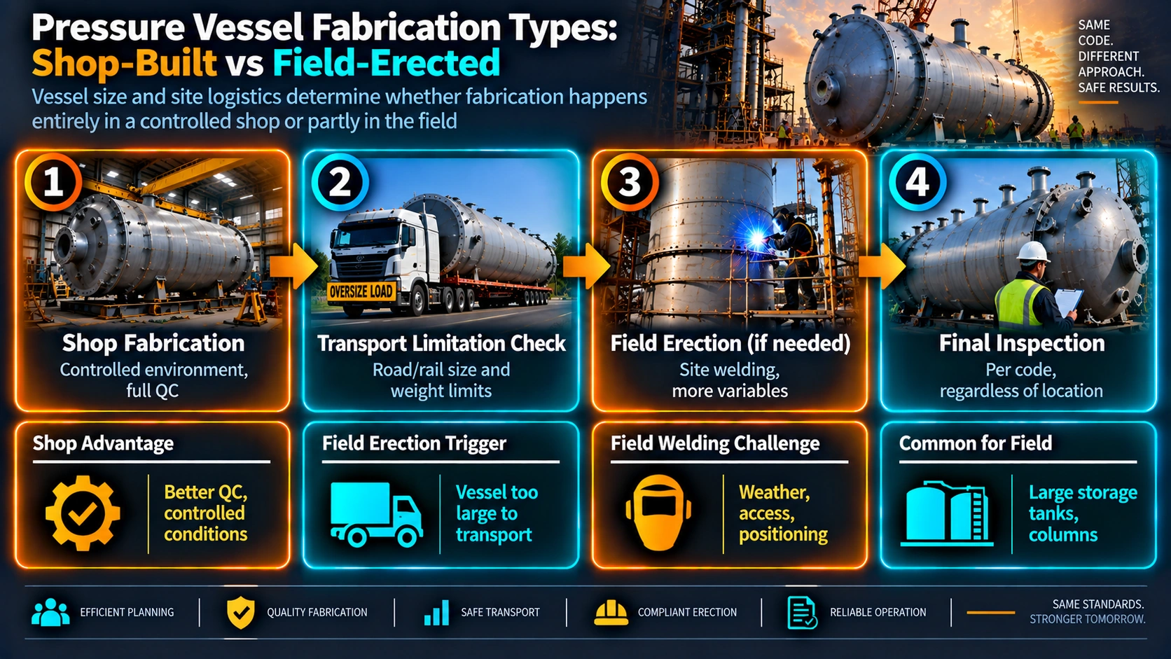
Per ASME Section VIII Division 1, a pressure vessel is a container designed to operate at internal pressures above 15 psig (approximately 103 kPa gauge). In practice the term covers a very wide range of equipment: separators, reactors, heat exchangers, air receivers, storage bullets, distillation columns, towers, boilers, and many other items. What distinguishes a pressure vessel from other piping or storage equipment is the combination of high operating pressure, elevated temperature, and the consequence of failure — all of which drive the need for documented material certification, controlled welding procedures, mandatory non-destructive examination, and third-party inspection.
Common Pressure Vessel Examples in Industry
The following list covers the most frequently encountered pressure vessels across the major process industries:
- Separators — two-phase (gas/liquid) and three-phase (gas/oil/water) vessels in upstream oil and gas production
- Reactors — fixed-bed catalytic reactors, hydroprocessing reactors, polymerisation reactors
- Heat Exchangers — shell-and-tube exchangers per TEMA, designed as pressure vessels on both shell and tube sides
- Air Receivers — compressed-air storage vessels in utilities and instrument air systems
- Storage Bullets & Spheres — LPG, propylene, and ammonia storage under pressure
- Distillation Columns & Towers — tall vertical vessels with internals for fractionation
- Boilers & Steam Drums — governed by ASME Section I or Section VIII depending on steam pressure
- Knockout Drums & Slug Catchers — inlet receiving vessels for pipeline slugs
Major Design Codes and Standards
| Code / Standard | Origin | Scope | Key Feature |
|---|---|---|---|
| ASME Section VIII Div. 1 | USA | Pressure vessels up to 3,000 psi (general) | Design by rule; widely accepted globally |
| ASME Section VIII Div. 2 | USA | High-pressure vessels, more rigorous analysis | Design by analysis; higher allowable stresses |
| EN 13445 | Europe | Unfired pressure vessels in CE-marked markets | Harmonised EU standard |
| PD 5500 | UK | Unfired fusion-welded pressure vessels | Widely used in UK and Middle East projects |
| API 510 | USA | In-service inspection of pressure vessels | Covers repair, alteration, re-rating |
| TEMA | USA | Shell-and-tube heat exchangers | Classes R, C, B for different service severity |
The Pressure Vessel Fabrication Process
Pressure vessel fabrication follows a well-defined sequence of nine major stages, each with its own quality control hold points and inspection activities. Deviating from this sequence — for example, performing fit-up before edge preparation is complete, or welding before preheat is verified — introduces risk of non-conformance that may require costly rework or vessel rejection. The nine stages are summarised below before each is discussed in detail.
Material Selection & Certification
Material grades, mill test certificates, heat numbers, and impact test results verified against design specification.
Cutting & Edge Preparation
Plates and shell sections cut to size; weld joint geometry machined or flame-cut to code-required bevel angle and root face.
Rolling & Forming
Shell courses rolled to the required diameter and roundness; heads formed as ellipsoidal, torispherical, or hemispherical profiles.
Fit-Up & Assembly
Shell courses, heads, nozzles, and internals positioned within code-specified tolerances for root gap, misalignment, and angular deviation.
Welding Operations
All welds executed per qualified WPS; preheat, interpass temperature, and heat input controlled throughout.
Non-Destructive Testing (NDT)
Welds examined by VT, RT or UT, MT/PT as required by code and NDE category; all defects repaired and re-examined.
Post Weld Heat Treatment (PWHT)
Vessel heated in furnace or locally per code-qualified procedure; temperature, rate, and soak time recorded on chart recorder.
Hydrostatic Testing
Vessel pressurised with water to 1.3 × MAWP; held for minimum duration; inspected for leaks and distortion.
Surface Preparation & Painting
External surfaces blast-cleaned to Sa 2.5; primer, intermediate, and topcoat applied to specified DFT per corrosion protection system.
Stage 1: Material Selection and Certification
Material selection for pressure vessels is governed by the design code, the process fluid, the operating temperature range, and any special service requirements such as sour (H2S) service, hydrogen service, or cryogenic service. The fabricator must obtain Material Test Reports (MTRs) — also called Mill Certificates — for all pressure-containing materials, verifying chemical composition, mechanical properties, heat treatment condition, and impact test results where required.
| Material Family | Typical Grades (ASME) | Temperature Range | Key Service Applications |
|---|---|---|---|
| Carbon Steel | SA-516 Gr 60 / 70 | −29°C to +425°C | General service, separators, storage |
| Low Alloy C-Mn Steel | SA-537 Cl.1 / Cl.2 | −46°C to +425°C | Low-temperature service vessels |
| Cr-Mo Low Alloy | SA-387 Gr 11/22/91 | Up to +600°C | Hydroprocessing reactors, boiler drums |
| Austenitic SS | SA-240 TP304L / 316L | −196°C to +450°C | Corrosive media, food/pharma, cryogenic |
| Duplex SS | SA-240 S31803 / S32205 | −50°C to +315°C | Chloride environments, offshore topside |
| Nickel Alloys | SB-443 Alloy 625; SB-424 825 | Cryogenic to +800°C | High-corrosion, acid service |
Stage 2: Cutting and Edge Preparation
Shell plates and head blanks are cut to the required dimensions using CNC plasma cutting, oxy-fuel flame cutting, or laser cutting. After cutting, all edges that will form weld joints must be prepared to the geometry specified in the approved WPS. This involves bevel angle machining (typically 30° or 37.5° for single or double V-grooves), root face dressing, and dimensional verification per code tolerances.
Proper edge preparation ensures full penetration welding is achievable — a requirement for all Category A and B seams in ASME Section VIII pressure vessels. Poor edge geometry leads to incomplete fusion, excessive reinforcement, or poor root profile, all of which are causes for weld rejection on radiographic examination.
Stage 3: Rolling and Forming
Shell courses are rolled from flat plates on three-roll or four-roll plate-rolling machines. The critical quality characteristics are:
- Roundness (Ovality): ASME VIII UG-80 limits the difference between maximum and minimum diameter at any cross-section to 1% of the nominal outside diameter.
- Diameter Tolerance: Must be within the tolerance specified in the vessel drawing, typically ±3 mm for vessels up to 2 m diameter.
- Peaking at the Longitudinal Seam: The flat area adjacent to the longitudinal weld due to the inability of the rolls to form the last 50–75 mm of plate must be controlled and measured.
- Alignment Accuracy: Longitudinal seam offset (hi-lo) must be within code limits — ASME VIII UW-33 limits offset to the lesser of 1/4 of the nominal shell thickness or 3.2 mm for butt joints.
Vessel heads are hot-formed or cold-pressed to the required profile — ellipsoidal (2:1), torispherical, or hemispherical. Cold-formed carbon steel heads must be stress-relieved (normalised or PWHT) if the cold work exceeds 5% in the outer fibre, per ASME VIII UCS-79.
Stage 4: Fit-Up and Assembly
Assembly involves joining the rolled shell courses to one another and attaching the formed heads, nozzles, manways, support saddles or skirts, and internal components. The critical dimensional parameters at this stage include root gap, angular misalignment, linear misalignment (hi-lo), and tack weld quality. All tack welds must be made by qualified welders using an approved WPS; they become part of the completed weld and must be fully fused and free of cracks.
Stage 5: Welding Operations
All pressure-containing welds must be performed in strict accordance with a Welding Procedure Specification (WPS) that has been qualified by a Procedure Qualification Record (PQR) per ASME Section IX. Every welder must hold a current Welder Performance Qualification (WPQ) covering the relevant material, process, position, and thickness range. Key welding controls include:
| Welding Parameter | Control Requirement | Consequence of Deviation |
|---|---|---|
| Preheat Temperature | Minimum per WPS; verified by thermocouple or contact pyrometer | Hydrogen cracking, HAZ hardness above code limit |
| Interpass Temperature | Maximum per WPS (typically 250°C for C-Mn steel) | Reduced toughness, grain coarsening |
| Heat Input | KJ/mm range per WPS; calculated from volts, amps, travel speed | Over-width HAZ, reduced impact values, burn-through |
| WPS / PQR | Essential variables not exceeded during production | Weld non-conformance; may require new PQR |
| Consumable Control | Correct brand/classification, baked per manufacturer spec | Hydrogen pick-up, porosity, segregation |
Common welding processes for pressure vessel fabrication include SMAW (Shielded Metal Arc Welding) for root passes and access-restricted areas, SAW (Submerged Arc Welding) for long circumferential and longitudinal seams, GTAW (TIG) for stainless steel root passes and overlay cladding, and GMAW/FCAW for structural attachments and nozzle welds.
Stage 6: Non-Destructive Testing (NDT)
The extent and type of NDE required is determined by the design code, the vessel’s NDE category (ASME VIII: RT-1, RT-2, RT-3), the material, and any supplementary requirements from the purchase specification. The principal NDE methods applied to pressure vessel welds are:
- Visual Testing (VT): 100% of all welds before any other NDE method. Checks for surface cracks, undercut, concavity, overlap, and incorrect weld profile per ASME VIII UW-35.
- Radiographic Testing (RT): Volumetric method for detecting internal defects (porosity, slag, LOF, cracks). Required for all full-penetration butt welds under full radiography (ASME VIII Div. 1) or spot radiography categories.
- Ultrasonic Testing (UT): Alternative to RT for thick-wall vessels (>50 mm) and for straight-beam thickness measurement. Phased Array UT (PAUT) increasingly specified for high-integrity vessels.
- Magnetic Particle Testing (MT): Surface and near-surface detection in ferromagnetic materials; applied to nozzle welds, structural attachments, and weld repairs.
- Dye Penetrant Testing (PT): Surface crack detection for non-magnetic materials (austenitic SS, nickel alloys, titanium).
For vessels requiring full radiography under ASME VIII Div. 1, the joint efficiency E = 1.0, enabling the minimum shell thickness to be calculated using the full material allowable stress. For spot radiography, E = 0.85; for no radiography, E = 0.70. The mechanical testing requirements for pressure vessel weld qualification are covered separately.
Stage 7: Post Weld Heat Treatment (PWHT)
PWHT is performed in a furnace or using electrical resistance heating elements attached locally to the vessel. The temperature profile is recorded on a multi-channel chart recorder connected to thermocouples placed on the vessel shell. Key PWHT parameters for carbon and low-alloy steels per ASME Section VIII are:
Stage 8: Hydrostatic Testing
Hydrostatic (proof pressure) testing is the final structural integrity verification. The vessel is filled completely with clean water, all vents are opened to expel air, and pressure is slowly raised to the test pressure. The test pressure for ASME Section VIII Div. 1 vessels is 1.3 times the Maximum Allowable Working Pressure (MAWP) at design temperature, multiplied by the ratio of allowable stress at test temperature to allowable stress at design temperature:
The vessel is held at test pressure for at least 30 minutes (or longer per code/spec). All joints, connections, and accessible surfaces are inspected for leaks, distortion, or signs of permanent deformation. No repairs may be made while the vessel is under pressure.
Stage 9: Surface Preparation and Painting
External surfaces are blast-cleaned to Sa 2.5 (ISO 8501-1) using steel shot or grit abrasive. The specified protective coating system — typically a three-coat system comprising inorganic zinc primer, epoxy intermediate coat, and polyurethane topcoat — is applied to the required dry film thickness (DFT). Coating thickness is verified by magnetic pull-off gauges. Internal surfaces in corrosive service may receive phenolic epoxy lining or electroless nickel plating depending on the process fluid specification.
Shell Thickness Design — Key Formulas
The minimum required shell thickness for a cylindrical or spherical pressure vessel is calculated from the design pressure, inside radius, allowable stress, and joint efficiency. Understanding these formulas is essential for any pressure vessel engineer, and forms a core part of the ASME Section VIII competency assessment.
Types of Pressure Vessels
Pressure vessels are classified in several different ways depending on the context: by geometric shape, by orientation of the major axis, by the direction of the dominant pressure loading, and by the form of end closure. Understanding these classifications helps the designer select the most structurally efficient and cost-effective vessel configuration for a given service.
Classification by Shape
1. Cylindrical Vessels
- Most widely fabricated geometry
- Efficient for moderate pressures and large L/D ratios
- Hoop stress governs: σH = PD/2t
- Simple to roll, weld, and inspect
- Applications: separators, reactors, storage tanks
2. Spherical Vessels
- Equal biaxial stress: σ = PD/4t (all directions)
- Half the wall thickness of equivalent cylindrical shell
- More expensive to fabricate (petals / orange segments)
- Applications: LPG spheres, NH3 storage, gas holders
- Diameters typically 10–25 m
3. Conical Vessels
- Tapered shell with half-apex angle α ≤ 30° (no reinforcement), ≤ 60° with knuckle ring
- Stress concentration at cone-to-cylinder junction
- Applications: hopper bottoms, cyclone separators, transition reducers
- Designed per ASME VIII UG-32(g) / App. 1-5
Classification by Orientation
| Orientation | Description | Typical Applications | Key Design Consideration |
|---|---|---|---|
| Horizontal | Major axis horizontal; supported on two saddle supports | Two-phase separators, heat exchangers, accumulators, storage bullets | Saddle reaction forces; local stress at horn of saddle (Zick analysis) |
| Vertical | Major axis vertical; supported on leg supports, skirt, or lug supports | Distillation columns, absorbers, deaerators, reactors with internals | Wind / seismic overturning moment; skirt buckling; foundation bolt design |
Classification by Pressure Condition
Internal Pressure Vessels
- Pressure acts from inside the shell outward
- Shell in tension — governed by hoop and longitudinal stress
- Most common configuration in process industry
- Designed per ASME VIII UG-27 shell formulas
External Pressure Vessels
- Pressure acts from outside inward — shell in compression
- Critical failure mode: elastic or plastic buckling collapse
- Design requires buckling analysis per ASME VIII UG-28 geometric charts
- Applications: jacketed reactors, vacuum columns, canned condensers
Classification by End Construction
Open-End Vessels
- Open at one or both ends during operation
- Atmospheric or process connection at open end
- Applications: filtration housings, flange-faced columns during operation
Closed-End (Fully Enclosed) Vessels
- Fully enclosed by heads at both ends — standard configuration
- Head types: ellipsoidal (2:1), torispherical, hemispherical, flat, conical
- All pressure-retaining nozzles, manways welded into shell or heads
Head Type Selection Guide
| Head Type | Stress Efficiency | Fabrication Cost | Typical Application | Code Reference |
|---|---|---|---|---|
| Hemispherical | Highest | Highest | High-pressure reactors, large-diameter vessels > 2 m | ASME VIII UG-32(f) |
| Ellipsoidal 2:1 | High | Moderate | Standard ASME pressure vessels, general service | ASME VIII UG-32(d) |
| Torispherical (Klopper) | Moderate | Low | Low to medium pressure vessels in EN 13445 / PD 5500 projects | EN 13445-3 §7.2 |
| Flat Plate | Low | Lowest | Low-pressure shell covers, heat exchanger tube sheets, manway covers | ASME VIII UG-34 |
| Conical | Medium | Moderate | Hopper bottoms, cyclone inlets, column boot sections | ASME VIII UG-32(g) |
Quality Control and Important Quality Controls
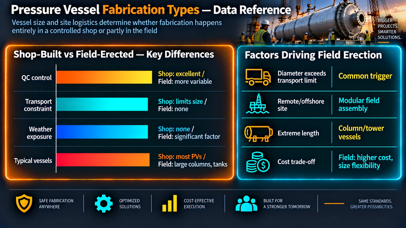
A robust quality management system is the backbone of compliant pressure vessel fabrication. The fabricator’s Quality Management System (QMS) must be certified to ISO 9001 and, for ASME-stamped vessels, hold the appropriate ASME Certificate of Authorisation (U, U2, or U3 stamp). Key quality controls throughout fabrication include:
- Material Traceability: Each pressure part must be traceable to its heat number and mill certificate throughout fabrication. Identification must be transferred before any cut is made to ensure no material can be mixed or lost.
- Dimensional Inspection: All formed components verified against isometric sketches and vessel drawings at each fabrication stage using calibrated instruments.
- Welding Control: WPS, PQR, and WPQ documentation reviewed by the Authorised Inspector (AI) before welding commences. Production weld test plates may be required for certain materials or services.
- NDE Qualification: All NDE personnel must hold Level II or Level III certification per SNT-TC-1A, ISO 9712, or PCN depending on the contract specification.
- Heat Treatment Records: All PWHT must be documented on calibrated chart recorders with thermocouple locations shown on a sketch. Records are retained as part of the vessel data book.
- Documentation & QA Records: The completed Manufacturer’s Data Report (MDR) / Data Book must contain material certs, WPS/PQR/WPQ records, NDE reports, PWHT charts, hydrotest record, dimensional inspection reports, and the ASME Code Report Form U-1A before the nameplate can be stamped and the vessel released.
Industrial Applications by Vessel Type
| Industry | Typical Vessels | Design Codes | Key Material Considerations |
|---|---|---|---|
| Oil & Gas Upstream | Three-phase separators, slug catchers, test separators, glycol contactors | ASME VIII Div. 1, NACE MR0175 | HIC-resistant plate for sour service; PWHT mandated |
| Petrochemical | Hydrocracker reactors, reformer charge heaters, high-pressure HP separators | ASME VIII Div. 2, API 934 | Cr-Mo steels; post-weld bake-out; temper embrittlement assessment |
| Power Generation | Steam drums, boiler headers, HP/LP feedwater heaters, deaerators | ASME Section I, ASME VIII | SA-516, SA-387 Gr22; 100% RT; steam service PWHT always required |
| LNG / Cryogenic | LNG storage tanks, cryogenic heat exchangers, vapourisers | ASME VIII Div. 1, EN 13458 | 9% Ni steel, SS 304L; impact testing at −196°C |
| Chemical | Distillation columns, absorption towers, neutralisation tanks | ASME VIII, EN 13445, PD 5500 | 316L, Duplex, lined vessels; ASTM G48 for duplex qualification |
| Pharmaceutical | Jacketed reactors, autoclaves, sterile vessels, mixing tanks | ASME BPE, ASME VIII | 316L electropolished; Ra surface finish ≤ 0.4 μm |
| Refinery | Crude distillation column, FCC regenerator, hydrotreater reactors, amine absorbers | ASME VIII Div. 2, API 579 | P91, P22, SS overlay; fitness-for-service assessment per API 579-1/ASME FFS-1 |
Recommended Books on Pressure Vessel Engineering
Frequently Asked Questions
What design codes govern pressure vessel fabrication?
The primary design codes for pressure vessels are ASME Section VIII Division 1 and Division 2 (widely used globally), API standards for oil and gas applications, TEMA standards for heat exchangers, PD 5500 (UK), and EN 13445 (European standard). The applicable code depends on the operating jurisdiction, industry, design pressure, and client specification. ASME Div. 2 permits higher allowable stresses through more rigorous analysis compared to Div. 1. For an in-depth review of code requirements, visit the ASME Section VIII quiz and study resource.
What materials are commonly used for pressure vessel construction?
The most common pressure vessel materials are carbon steel (SA-516 Gr 60/70), low-alloy steels (SA-387 Cr-Mo grades for high-temperature service), austenitic stainless steels (316L, 304L for corrosion resistance), duplex stainless steels (2205 for combined corrosion-erosion environments), and nickel alloys (Alloy 625, Alloy 825) for highly corrosive or cryogenic service. Material selection depends on design pressure, design temperature, process fluid corrosivity, and hydrogen service requirements. See the P-Number and material grouping guide for the ASME Section IX classification of pressure vessel materials.
Why is PWHT required for pressure vessels?
Post Weld Heat Treatment (PWHT) is performed to reduce residual welding stresses, improve toughness and ductility of the weld and heat-affected zone, reduce hardness to acceptable code limits, and prevent hydrogen-induced cracking in susceptible steels. ASME Section VIII and applicable codes mandate PWHT based on material P-Number, thickness thresholds, and service conditions such as hydrogen or sour environments. For carbon steel (P-No. 1), PWHT is mandatory above 38 mm nominal weld thickness under ASME VIII UCS-56.
What is the purpose of hydrostatic testing for pressure vessels?
Hydrostatic testing verifies the structural integrity, leak-tightness, and load-bearing capacity of a completed pressure vessel before it enters service. The vessel is filled with water and pressurised to 1.3 times the Maximum Allowable Working Pressure (MAWP) under ASME VIII Div. 1, adjusted for the ratio of allowable stress at test temperature to design temperature. Water is used because it is incompressible and releases far less stored energy than gas in the event of a failure, making hydrotesting significantly safer than pneumatic testing at comparable pressures.
What NDT methods are applied to pressure vessel welds?
Pressure vessel welds are typically subjected to Visual Testing (VT) as the baseline inspection, Radiographic Testing (RT) for volumetric weld quality, Ultrasonic Testing (UT) including phased array (PAUT) for thickness measurement and flaw detection, Magnetic Particle Testing (MT) for surface and near-surface flaws in ferromagnetic materials, and Dye Penetrant Testing (PT) for surface-breaking defects in non-ferromagnetic materials. The required combination and extent of examination is specified by the design code and NDE examination category, which determines whether RT is 100%, spot, or not required. Review the mechanical testing guide for complementary destructive testing requirements.
What are the main differences between spherical and cylindrical pressure vessels?
Spherical pressure vessels distribute internal pressure uniformly in all directions, resulting in the lowest possible wall thickness for a given pressure and volume — approximately half the wall thickness required by a cylindrical vessel of the same diameter. However, spherical vessels are significantly more expensive and complex to fabricate because the shell must be formed from multiple curved petal sections. Cylindrical vessels are easier and cheaper to manufacture, transport, and maintain, making them by far the most commonly used geometry. Spherical vessels are used for large-volume, high-pressure storage of LPG, propylene, and ammonia where the material saving justifies the fabrication cost premium.
How is head type selection made for a pressure vessel?
Head type is selected based on design pressure, temperature, vessel diameter, and cost considerations. Hemispherical heads are structurally the most efficient (lowest stress concentration) but are the most expensive to form and are used mainly for high-pressure, large-diameter vessels where material saving outweighs fabrication cost. Ellipsoidal 2:1 heads offer a good balance of efficiency and cost and are the standard choice for most ASME Section VIII vessels. Torispherical heads are cheaper to form but less efficient and are common in EN 13445 and lower-pressure applications. Flat heads are used at low pressures or for access covers. Conical heads are used at vessel transitions, separator boot sections, and cyclone inlets.
What is the difference between internal and external pressure vessels?
Internal pressure vessels resist pressure from fluid or gas inside the shell, placing the shell in tension — this is the most common configuration. External pressure vessels must resist pressure applied from outside, placing the shell in compression and creating a risk of buckling collapse rather than tensile failure. External pressure design uses ASME VIII UG-28 geometric charts to determine the critical buckling pressure based on L/D and D/t ratios, and stiffening rings are often added to reduce the unsupported length. Typical external pressure applications include jacketed reactors, vacuum distillation columns, and canned condensers.