What is Crack Tip Opening Displacement (CTOD) Testing?
Crack Tip Opening Displacement (CTOD) testing is one of the most rigorous and meaningful methods available for quantifying the fracture toughness of a material — in particular, the fracture toughness of welded joints and their heat-affected zones. In high-consequence industries such as offshore oil and gas, subsea pipelines, LNG terminals, nuclear power, and pressure vessel fabrication, the ability to predict how a crack will behave under real service loads is not a theoretical exercise. It is an engineering requirement that underpins structural integrity programmes, fitness-for-service assessments, and welding procedure qualification.
Unlike the Charpy V-notch impact test — which measures energy absorbed during a single high-speed impact — CTOD provides a geometrically defined, rate-controlled measure of toughness directly linked to the mechanics of crack initiation and stable crack extension. The result, expressed in millimetres of crack-tip opening, can be fed directly into fracture mechanics calculations to determine maximum permissible flaw sizes and safe operating loads. This makes CTOD a cornerstone of both mechanical testing in ASME Section IX qualification programmes and fitness-for-service evaluations conducted under BS 7910 and API 579.
This guide covers everything a welding engineer, materials engineer, or inspection professional needs to know about CTOD: the underlying fracture mechanics, specimen geometry, test procedure, relevant standards, result interpretation, acceptance criteria, and practical applications across industry.
Fundamentals of Fracture Mechanics and Why CTOD Matters
To understand CTOD, it helps to appreciate the two primary regimes of fracture mechanics. In Linear Elastic Fracture Mechanics (LEFM), toughness is characterised by the stress intensity factor K, which describes the stress field singularity at a crack tip in a purely elastic material. Once the applied K reaches the critical value KIc, fracture occurs. This approach works well for high-strength, relatively low-toughness materials where the plastic zone ahead of the crack tip is small compared to specimen dimensions.
However, structural steels — especially weld metals and HAZ microstructures — exhibit significant plasticity before fracture. In these materials, the small-scale yielding assumption of LEFM breaks down. Elastic-Plastic Fracture Mechanics (EPFM) is needed, and two parameters dominate: the J-integral (an energy-based parameter) and the Crack Tip Opening Displacement. CTOD has the practical advantage that it is directly measurable on a test specimen using a clip gauge — no post-test calculation involving crack length increments is strictly required.
The physical significance is intuitive: a blunting crack tip is a tough crack tip. When a material is tough, the crack tip blunts as load increases, absorbing energy. When a material is brittle — as in the coarse-grained HAZ after a high-heat-input weld pass, or in a hydrogen-embrittled zone in sour service — the crack tip remains sharp and fracture initiates at very low displacements. CTOD captures this difference quantitatively.
CTOD and Its Relationship to K and J-Integral
For elastic conditions, CTOD (δ) can be related to the stress intensity factor K and the yield strength σY through:
In practice, CTOD test standards (BS 7448, ASTM E1820, ISO 15653) use a two-component formula to calculate CTOD from the measured load and clip gauge displacement, separating the elastic component (derived from load) from the plastic component (derived from plastic area under the load-displacement curve). This is more accurate than simple elastic conversions, especially at high toughness levels where plastic deformation dominates.
Elastic component: δ_el = (K² ⋅ (1 – ν²)) / (2 ⋅ σ_Y ⋅ E)
Plastic component: δ_pl = 0.4 ⋅ (W – a) ⋅ V_p / (0.4⋅W + 0.6⋅a + z) W = specimen width, a = crack length, V_p = plastic clip gauge displacement z = distance of clip gauge knife edge above specimen surface Final CTOD (δ) reported in millimetres.
When is CTOD Testing Required?
CTOD testing is not universally mandated by base codes such as ASME Section IX or AWS D1.1, but it is commonly required by supplementary project specifications, client standards, and industry-specific codes. Understanding when to invoke CTOD testing — and when Charpy testing alone is adequate — is important for specification writers and welding engineers alike.
| Situation / Trigger | Typical Requirement | Applicable Document |
|---|---|---|
| Offshore structural welded joints (jacket, topside) | CTOD on weld metal and HAZ at minimum design temperature | ISO 19902, NORSOK M-120, client spec |
| Subsea pipeline girth welds | SENT testing at minimum design temperature | DNV-ST-F101, ExxonMobil GP 18-10 |
| Pressure vessels for low-temperature service (<-46°C) | CTOD on HAZ to supplement Charpy requirements of UG-84 | ASME VIII + client spec |
| Sour service piping and vessels (H&sub2;S environments) | CTOD at relevant temperature to assess hydrogen embrittlement risk | NACE MR0175 / ISO 15156, client spec |
| Fitness-for-service assessment of flawed components | CTOD to provide Kmat input for fracture assessment | BS 7910, API 579-1/ASME FFS-1 |
| PQR qualification for high-integrity welds | CTOD at test temperature specified in WPS/PQR requirements | Project PQR requirements |
| High-strength steels (yield >460 MPa) | CTOD where brittle HAZ behaviour is a concern | EN 1011-2, project spec |
CTOD Specimen Types — SENB, SENT, and CT
The geometry of the test specimen has a major influence on the constraint at the crack tip and therefore on the CTOD value obtained. Three specimen types are in common use, and selection must be made carefully to ensure the test result is representative of the structural situation being assessed.
Single Edge Notched Bend (SENB)
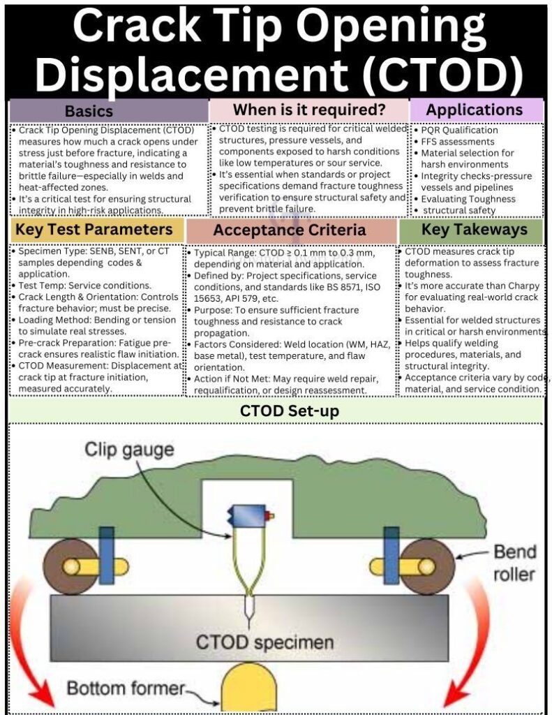
The SENB specimen — also called the three-point bend specimen — is specified in BS 7448 Part 1 and ISO 15653 and is the most widely used geometry for weld procedure qualification. The specimen is rectangular in cross-section, with a machined notch and fatigue pre-crack on one face. It is loaded in three-point bending between rollers. The SENB specimen imposes high crack-tip constraint (close to plane-strain conditions), making it a conservative test. This conservatism is appropriate for most structural integrity assessments where the worst-case toughness is required.
Single Edge Notched Tension (SENT)
The SENT specimen is loaded in uniaxial tension rather than bending. The lower bending constraint at the crack tip means SENT produces higher CTOD values than SENB for the same material — it is less conservative. This is not a shortcoming; for pipeline girth welds in tension-dominated loading (as during reeling or seabed settlement), SENB over-conservatism would impose unrealistically tight weld quality requirements. SENT testing is specified by DNV-ST-F101 and industry standards from operators such as ExxonMobil, Shell, and BP. ASTM E3174 provides a standard test method for SENT.
Compact Tension (CT)
The CT specimen is compact and square, loaded in tension via pins through holes at the back of the specimen. It is efficient in material use and is commonly used for base metal KIc and fracture toughness characterisation in ASTM E399 and ASTM E1820. CT specimens are less commonly used for weld and HAZ testing in the oil and gas sector, as the weld cross-section geometry makes it difficult to extract CT specimens with the crack tip oriented in the target microstructure.
SENB — Use When
- Weld procedure qualification per BS 7448 / ISO 15653
- Conservative HAZ toughness required
- Project spec does not specify SENT
- Bending-dominated structural loading
SENT — Use When
- Pipeline girth welds under tension loading
- Reeling / strain-based design pipelines
- DNV-ST-F101 or operator standard requires SENT
- Less conservative toughness is technically justified
CTOD Test Procedure — Step by Step
A complete CTOD test programme involves several stages, from specimen extraction through fatigue pre-cracking, testing at temperature, and post-test examination. Each stage must be controlled to produce valid, defensible results.
Step 1: Specimen Extraction and Dimensional Preparation
Specimens are extracted from the test piece (a welded coupon representing the production weld) by machining. The specimen orientation and notch location are defined by the test specification. For HAZ testing, the notch is typically located at the fusion line or at a defined distance from it to sample the coarse-grained HAZ. Full-thickness specimens are preferred where the plate or pipe wall thickness allows; sub-size specimens are used where thickness is insufficient, with corrections applied.
Step 2: Fatigue Pre-Cracking
A mechanically sharp fatigue crack is grown from the tip of the machined notch under cyclic loading. The pre-crack must be straight, symmetric, and of the required length ratio (a/W typically 0.45 to 0.55 per BS 7448). The maximum fatigue pre-cracking load is strictly limited to ensure no plastic deformation ahead of the crack tip from the pre-cracking cycle biases the result. For weld and HAZ specimens, it is important that the fatigue crack front is in the intended microstructure.
Step 3: Side Grooving (Optional)
Side grooves machined symmetrically on the side faces of the specimen (typically removing 12.5% of the total thickness from each side, for 25% total) are used to promote a straight crack front during testing, particularly for tougher materials. Side grooving reduces the tendency for shear lip formation at the specimen edges, producing a more representative plane-strain crack front.
Step 4: Testing at Temperature
The specimen is cooled (or heated) to the specified test temperature in a controlled environment chamber. Temperature must be stable at ±2°C of the target for the required soak period before loading. The clip gauge is mounted at the notch mouth. Loading is applied at a rate within the standard’s requirements (quasi-static), and the load-displacement curve is recorded continuously throughout the test.
Step 5: Result Classification and CTOD Calculation
The load-displacement record is examined to determine the failure mode and identify the critical event (pop-in, maximum load, or stable fracture). The appropriate CTOD value (δc, δu, or δm) is then calculated using the two-component formula. A valid test requires the crack dimensions and crack front straightness to be within the tolerances of the standard, confirmed by measurement of the broken specimen halves.
Step 6: Post-Test Metallographic Examination
For HAZ tests, a section through the specimen thickness is prepared and etched to confirm the position of the crack front relative to the weld fusion line and HAZ sub-zones. This is essential: if the crack did not sample the intended microstructure (e.g., it deviated into the weld metal or base metal), the test result must be qualified or rejected as non-representative. Post-test macro documentation is a standard deliverable in most industry test reports.
Interpreting CTOD Results — delta-c, delta-u, and delta-m
The type of CTOD value reported depends on the shape of the load-displacement record and the failure mode observed. BS 7448 and ISO 15653 define three critical events:
| CTOD Value | Symbol | Failure Mode | Nature | Conservatism |
|---|---|---|---|---|
| Critical CTOD | δc | Unstable fracture or pop-in at or before maximum load, with no prior stable tearing | Cleavage or brittle | Most conservative |
| CTOD at unstable fracture after stable tearing | δu | Unstable fracture after stable ductile crack extension; load drops suddenly | Ductile-to-brittle transition | Intermediate |
| Maximum load CTOD | δm | Maximum load attained with no instability or pop-in; ductile fracture | Fully ductile | Least conservative |
Pop-in events — sudden partial instabilities visible as load drops on the record — require careful evaluation. A pop-in may represent crack arrest at a tough region after initiation in a locally brittle zone (LBZ), or it may reflect test artefacts (e.g., ice on the specimen at low temperature). Pop-in evaluation criteria are specified in BS 7448; not all pop-ins disqualify a result.
CTOD Acceptance Criteria — Standards and Typical Values
There is no single universal CTOD acceptance criterion. The required minimum CTOD depends on the material, the weld zone tested, the test temperature, the applied stress, the assumed flaw size, and the governing standard or project specification. The following table summarises typical requirements encountered in practice:
| Application / Sector | Typical Minimum CTOD | Test Temperature | Standard / Driver |
|---|---|---|---|
| Offshore structural steel joints | 0.15 mm (HAZ), 0.25 mm (WM) | Min. design temp. or -10°C | NORSOK M-120, ISO 19902 |
| Subsea pipeline (DNV) | Per fracture mechanics assessment | -20°C typical | DNV-ST-F101 |
| Pressure vessels (cryogenic) | 0.10 mm minimum (weld + HAZ) | Design temperature | Client specification |
| Sour service vessels / piping | 0.20 mm (HAZ FL notch) | -10°C or MDMT | Client / NACE |
| FFS assessment (BS 7910) | Derived from fracture mechanics; no fixed minimum | Service temperature | BS 7910, API 579 |
| High-strength structural steel (>460 MPa) | 0.25 mm at -20°C (common client requirement) | -20°C | Client spec / EN 1993 |
Where acceptance criteria are not met, the options available to the engineer include: re-qualification of the welding procedure with modified heat input, preheat, or interpass temperature; selecting alternative consumables with higher notch toughness; performing a fracture mechanics assessment to demonstrate fitness for service at the actual measured toughness level; or structural redesign to reduce applied stress or flaw tolerance requirements.
CTOD Testing Versus Charpy Impact Testing — A Technical Comparison
Both Charpy and CTOD measure a material’s resistance to fracture, but they do so in fundamentally different ways and provide different types of information. Understanding the relationship — and limitations — of each test is essential for a complete fracture toughness assessment strategy. For a full treatment of mechanical testing methods including Charpy requirements in ASME Section IX, refer to our dedicated guide.
| Feature | Charpy Impact Test | CTOD Test |
|---|---|---|
| Parameter measured | Energy absorbed (Joules) | Crack tip opening (mm) |
| Loading rate | Dynamic (high strain rate) | Quasi-static (slow) |
| Fracture mechanics basis | Empirical / comparative | Directly applicable in EPFM |
| Specimen notch type | V-notch (no pre-crack) | Fatigue pre-crack |
| Specimen size | 10 x 10 x 55 mm (standard) | Full-thickness (up to B = W) |
| Use in FFS assessment | Only via empirical correlations | Direct input to BS 7910 / API 579 |
| Cost and complexity | Low; routine | High; specialised laboratory |
| Code mandate | Widely mandated (ASME UG-84, ASME IX) | Project / client specification |
| HAZ notch targeting | Limited (3 specimens, macro confirmed) | Precise; fusion-line or specified location |
| Temperature characterisation | Series at multiple temperatures | Typically one or few temperatures |
In summary, Charpy testing remains the standard screening tool for toughness verification in routine weld procedure qualification and production testing. CTOD testing is the tool of choice when a quantitative fracture mechanics assessment is required, when HAZ toughness is a primary concern in critical applications, or when a fitness-for-service evaluation demands reliable Kmat input data.
Industrial Applications of CTOD Testing
CTOD is applied across a wide range of industries and project phases. Its value is greatest where the consequences of fracture are severe and where conventional toughness testing does not provide sufficient quantitative information.
PQR Qualification for Critical Welded Structures
When welding procedures for offshore jackets, FPSO hull structures, or topside structural nodes are qualified, project specifications routinely require CTOD testing of the weld metal, HAZ (fusion line notch), and sometimes the base metal. Results are benchmarked against acceptance criteria in the project specification or relevant design standard. Failure at PQR stage is far preferable to discovering inadequate toughness in a completed structure.
Fitness for Service (FFS) of Flawed Components
When in-service inspection detects crack-like flaws (e.g., hydrogen-induced cracking in a pressure vessel nozzle, fatigue cracks in a structural weld, or stress corrosion cracks in a pipeline), a fitness-for-service assessment determines whether the component can safely continue in service until the next planned shutdown. The assessment requires fracture toughness input, and CTOD data from test coupons representing the material and weld condition provides this. CTOD-based FFS using BS 7910 or API 579 is the industry standard approach for this.
Sour Service and Hydrogen Embrittlement Assessment
In hydrogen sulphide-containing environments, steels can suffer hydrogen-induced cracking (HIC) and sulphide stress cracking (SSC). CTOD testing in conjunction with sour service assessment programmes helps determine the fracture toughness margin available against hydrogen-assisted cracking. Low CTOD values at the HAZ may indicate susceptibility and trigger changes to the welding procedure or PWHT requirements. Sour service considerations also apply to understanding corrosion mechanisms that can nucleate cracks in service.
Pipeline Reeling and Strain-Based Design
Deep-water pipelines installed by the reeling method are subjected to plastic strains during installation that can challenge girth weld toughness. SENT-based CTOD testing, combined with strain capacity models (e.g., ECA per DNV-ST-F101), allows engineers to define the maximum tolerable weld flaw size for reeling installation — directly driving AUT acceptance criteria at the fabrication yard.
Material Selection and Development
When selecting steel grades for critical low-temperature service (e.g., LNG storage at -165°C, arctic pipelines at -60°C), CTOD testing forms part of the material qualification programme. Weldability trials with candidate consumables are followed by CTOD tests at the service temperature to rank materials and select the best-performing combination. This is closely related to understanding the metallurgy of duplex stainless steels and other high-alloy materials that present weldability challenges.