In the field of mechanical engineering, machining, and precision measurement, a micrometer is one of the most essential tools. It allows technicians and engineers to measure very small dimensions with high accuracy—something a vernier caliper or a simple scale may not achieve. Whether used in workshops, laboratories, or quality inspection departments, a micrometer plays a vital role in ensuring precision.
This article explains in detail how to read a micrometer, the concept of its scale system, and its practical uses in industries.
What is a Micrometer?
A micrometer, often called a micrometer screw gauge, is a precision measuring instrument that works on the principle of a finely threaded screw. When the spindle moves forward or backward by rotating the thimble, it advances or retracts by a fixed distance. This controlled motion allows for accurate measurement of small objects like wire thickness, sheet metal, or small machine components.
Micrometers are typically calibrated in millimeters (mm) or inches, with accuracy up to 0.01 mm (in metric) or 0.001 inch (in imperial).
Main Parts of a Micrometer
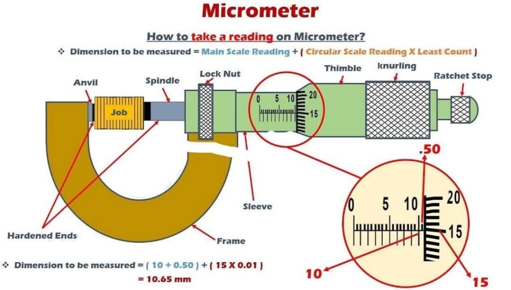
From the attached diagram, a micrometer consists of the following parts:
- Frame – Provides the C-shaped rigid structure.
- Anvil – The stationary contact point.
- Spindle – The movable measuring contact.
- Sleeve (Barrel) – Contains the main scale reading.
- Thimble – Rotating cylindrical part with circular scale.
- Ratchet Stop – Ensures uniform measuring pressure.
- Lock Nut – Locks the spindle in place after measurement.
Least Count of a Micrometer
Before learning how to take a reading, it’s important to understand the least count.
- Pitch of screw = Distance spindle moves forward in one full rotation of thimble. Usually, 0.5 mm.
- Number of divisions on thimble = 50 divisions.
- Least Count (L.C.) = Pitch ÷ Number of divisions = 0.5 ÷ 50 = 0.01 mm.
This means each division on the circular scale represents 0.01 mm.
How to Take a Reading on Micrometer
The measurement in a micrometer is obtained by combining the Main Scale Reading (MSR) and the Circular Scale Reading (CSR) multiplied by the Least Count.
Formula: Reading=MSR+(CSR×Least Count)\text{Reading} = \text{MSR} + (\text{CSR} \times \text{Least Count})Reading=MSR+(CSR×Least Count)
Step-by-Step Procedure
- Place the Job – The object (wire, plate, etc.) is placed between the anvil and spindle.
- Tighten with Ratchet – Rotate the thimble using the ratchet stop until the spindle just touches the job with correct pressure.
- Read Main Scale (MSR) – Check the last visible reading on the main scale (on the sleeve). Example: 10 mm.
- Check Half-Millimeter – Many micrometers also show a 0.5 mm line (above the main scale). If visible, add 0.5 mm.
- Read Circular Scale (CSR) – Look at the line on the thimble that coincides with the reference line on the sleeve. Example: 15 divisions.
- Multiply by Least Count – Multiply CSR with least count (15 × 0.01 = 0.15 mm).
- Add All Values – Final measurement = MSR + 0.5 (if applicable) + (CSR × LC).
Example from Attached Image
- Main Scale Reading (MSR) = 10 mm
- Half-Millimeter Line = 0.5 mm
- Circular Scale Reading (CSR) = 15 divisions
- Least Count (LC) = 0.01 mm
Reading=MSR+(CSR×Least Count)
Thus, the object measured is 10.65 mm thick.
Common Types of Micrometers
- Outside Micrometer – For measuring external dimensions (thickness, diameter).
- Inside Micrometer – For measuring internal dimensions like hole diameters.
- Depth Micrometer – For measuring depths of slots, holes, or recesses.
- Digital Micrometer – Provides direct reading on LCD, avoiding manual calculation errors.
Uses of Micrometer
Micrometers are indispensable in industries and laboratories for:
- Manufacturing & Machining – Measuring parts with high precision during production.
- Quality Control – Ensuring tolerance limits of manufactured components.
- Mechanical Engineering – Measuring wire, rods, thin sheets, bearings, shafts, etc.
- Aerospace & Automotive – High-precision measurement of engine and aircraft parts.
- Scientific Research – Where accurate measurements are critical.
Advantages of Micrometer
- High accuracy (up to 0.01 mm).
- Simple to use once understood.
- Reliable for small-scale precision measurement.
- Portable and durable.
Limitations of Micrometer
- Can measure only small dimensions compared to vernier calipers.
- Requires careful handling to avoid zero error or parallax error.
- Manual reading errors possible unless using a digital version.
Conclusion
The micrometer is an indispensable tool in precision engineering. By learning how to correctly read the main scale and circular scale using the formula: Reading= Reading=MSR+(CSR×LC)
technicians can ensure highly accurate measurements. With applications ranging from workshops to aerospace industries, the micrometer stands as a symbol of precision and accuracy in measurement.