Pipe vs Tube: Key Differences Every Engineer and Fabricator Must Know
The difference between pipe and tube is one of the most frequently misunderstood distinctions in engineering and industrial procurement. Although the two terms are used interchangeably in everyday speech, pipe and tube are defined, manufactured, and specified in fundamentally different ways — and selecting the wrong product can lead to flow restrictions, structural failures, code non-compliance, and unnecessary cost. This guide explains the dimensional basis of each product, covers the relevant standards, walks through practical selection criteria, and includes a quick-reference dimension lookup tool for common pipe sizes.
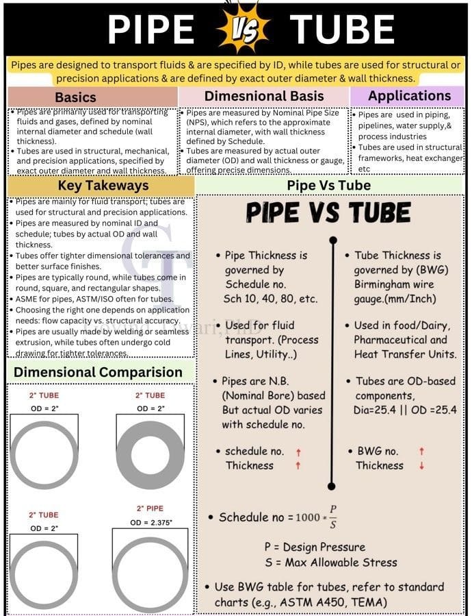
At the heart of the distinction is a single question: what dimension is the guaranteed, controlled dimension? For a pipe, it is the outside diameter (OD) — fixed by nominal size — while the inside diameter varies with wall thickness (schedule). For a tube, the outside diameter is also the guaranteed dimension, but it is expressed as an exact measurement, not a nominal approximation. That difference in how dimensions are stated flows into every downstream decision: fitting compatibility, pressure rating, weight estimation, and the applicable inspection standard.
Quick Reference: NPS Pipe Dimension Lookup
Use this tool to quickly retrieve the outside diameter, wall thickness, and inside diameter for common NPS pipe sizes and schedules per ASME B36.10M (carbon steel) and B36.19M (stainless steel).
NPS Pipe Dimension Lookup
Dimensional Basis: How Pipe and Tube Are Measured
Nominal Pipe Size (NPS) and Pipe Schedule
Nominal Pipe Size (NPS) is a North American designation system for pipe dimensions. The word “nominal” is key: for pipe sizes NPS 1/8 through NPS 12, the nominal designation does not directly equal either the actual OD or the actual ID. Instead, NPS is a legacy identifier that was originally approximately equal to the bore of standard-wall pipe. The actual OD for each NPS is a fixed value defined in ASME B36.10M, and it does not change regardless of wall thickness (schedule).
The Schedule number is calculated from the design relationship:
Common schedules in use today include: Sch 10S, 10, 20, 40 (Standard), 60, 80 (Extra Strong), 100, 120, 140, 160, and XXS (Double Extra Strong). Not every schedule exists for every NPS — the available schedule range varies by pipe size. This is why the ASME B36.10M table is an essential reference document for any piping engineer.
Worked Example: 2-inch NPS Pipe Across Schedules
| NPS 2 Pipe | OD (mm) | OD (in) | Wall (mm) | Wall (in) | ID (mm) | ID (in) | Application Indication |
|---|---|---|---|---|---|---|---|
| Schedule 10S | 60.33 | 2.375 | 2.77 | 0.109 | 54.79 | 2.157 | Low pressure |
| Schedule 40 (STD) | 60.33 | 2.375 | 3.91 | 0.154 | 52.51 | 2.067 | General service |
| Schedule 80 (XS) | 60.33 | 2.375 | 5.54 | 0.218 | 49.25 | 1.939 | High pressure |
| Schedule 160 | 60.33 | 2.375 | 8.74 | 0.344 | 42.85 | 1.687 | Very high pressure |
| XXS | 60.33 | 2.375 | 11.07 | 0.436 | 38.19 | 1.503 | Extreme service |
Notice that the OD (60.33 mm / 2.375 in) is identical for all schedules. Only the wall thickness and therefore the internal bore change. This constant-OD principle is what allows the same flange, fitting, or coupling to be used with any schedule of the same NPS.
Tube: Exact OD and Wall Thickness (or BWG)
A tube is defined by its actual outside diameter — not a nominal approximation. When you order a 2-inch tube, you receive material with an OD of exactly 2.000 inches (50.80 mm), held to tighter tolerances than pipe. Wall thickness is specified either as a decimal inch or mm value, or using the Birmingham Wire Gauge (BWG) system.
Birmingham Wire Gauge (BWG) — Heat Exchanger Tube Thickness
The BWG system is a legacy wire gauge standard still widely used in the process industry — particularly for specifying heat exchanger tubes. Higher BWG number = thinner wall. The commonly encountered range for heat exchanger tubes is BWG 10 through BWG 22.
| BWG Gauge | Wall Thickness (in) | Wall Thickness (mm) | Typical Application |
|---|---|---|---|
| BWG 10 | 0.134 | 3.40 | Heavy-duty / corrosive service |
| BWG 12 | 0.109 | 2.77 | High-pressure HX |
| BWG 14 | 0.083 | 2.11 | Standard HX duty |
| BWG 16 | 0.065 | 1.65 | Standard HX duty |
| BWG 18 | 0.049 | 1.24 | Low-pressure / clean service |
| BWG 20 | 0.035 | 0.89 | Thin wall / special applications |
| BWG 22 | 0.028 | 0.71 | Minimum wall |
Highlighted rows (BWG 14 and BWG 16) represent the most commonly specified gauges for general process heat exchangers. TEMA (Tubular Exchanger Manufacturers Association) standards specify minimum wall thickness requirements based on service conditions, corrosion allowance, and tube OD. For tube-to-tubesheet welding qualifications under ASME Section IX, see our dedicated guide on tube-to-tubesheet welding qualification.
Cross-Section Comparison: Pipe vs Tube
Applications: Where Pipe and Tube Are Used
Pipe is the primary choice wherever the function is conveying a fluid or gas from one point to another. The design emphasis is on internal pressure containment, flow capacity, and connection to flanges, valves, and fittings.
- Oil and gas transmission pipelines (API 5L)
- Refinery and petrochemical process piping (ASME B31.3)
- Power plant steam and feedwater systems (ASME B31.1)
- Water distribution and sewage systems
- HVAC refrigerant and chilled water piping
- Chemical plant process lines
- Offshore platform production headers
Tubing is chosen wherever the application demands dimensional precision, superior surface finish, or structural properties in addition to — or instead of — fluid transport.
- Heat exchanger and boiler tubes (ASTM A213, A179)
- Instrument and control lines
- Hydraulic and pneumatic systems
- Automotive fuel and brake lines
- Aerospace structural members
- Food, dairy, and pharmaceutical processing
- Structural hollow sections (square, rectangular)
- Condenser and feedwater heater bundles
For pressure piping applications, understanding the types of welded joints used in pipe fabrication and the appropriate welding symbols on fabrication drawings are essential competencies alongside material selection.
Selection Flowchart: Pipe or Tube?
Applicable Standards: Pipe and Tube
Pipe Standards
| Standard | Covers | Grade / Type | Typical Service |
|---|---|---|---|
| ASTM A106 | Seamless carbon steel pipe | Grade A, B, C | High temp process |
| ASTM A53 | Welded and seamless pipe | Type E (welded), Type S (seamless), Grade A & B | General utility |
| API 5L | Line pipe for transmission | X42 to X80 (SMYS designation) | Gas / oil pipelines |
| ASTM A335 | Alloy steel pipe | P1, P5, P9, P11, P22, P91 | High temp / high press |
| ASTM A312 | Austenitic stainless pipe | TP304, TP316, TP321, TP347 | Corrosive / cryogenic |
For pipes in sour service (wet H2S environments), additional material qualification under NACE MR0175 / ISO 15156 is required beyond the base ASTM specification. Similarly, stainless steel pipes in aggressive chloride environments require careful material selection to avoid weld decay and sensitisation.
Tube Standards
| Standard | Covers | Key Grades | Application |
|---|---|---|---|
| ASTM A213 | Alloy steel HX/boiler tubes | T11, T22, T91, TP304, TP316 | Heat exchangers, boilers |
| ASTM A179 | Low-carbon steel HX tubes | Single grade (0.06–0.18% C) | Condensers, coolers |
| ASTM A269 | Austenitic SS general tubing | TP304, TP316L | Instrument / process |
| ASTM A500 | Structural cold-formed tubing | Grade A, B, C | Structural hollow sections |
| ASTM A519 | Mechanical tubing | 1010 to 4130 alloys | Automotive, machinery |
For high-temperature heat exchanger tube materials such as T91 (9Cr-1Mo-V), the same special welding considerations that apply to P91 pipe welding also apply to T91 tube welding — including preheat, interpass temperature control, and mandatory PWHT.
Comprehensive Comparison: Pipe vs Tube
| Feature | Pipe | Tube |
|---|---|---|
| Dimensional basis | Nominal Pipe Size (NPS) + Schedule — OD is fixed, ID varies | Actual OD + wall thickness (decimal) or BWG gauge |
| Does the nominal size equal the OD? | No — for NPS <14, nominal ≠ OD. Above NPS 14, nominal = OD in inches | Yes — nominal size equals actual OD exactly |
| Primary purpose | Fluid and gas transport (pressure containment) | Structural, heat transfer, precision mechanical |
| Dimensional tolerances | Standard tolerances per ASME B36.10M | Tighter tolerances — essential for fitting clearances and HX tube rolling |
| Available cross-sections | Circular only (for pressure service) | Circular, square, rectangular, oval (structural grades) |
| Surface finish | Standard mill finish; ERW weld seam visible on welded pipe | Improved surface finish; often bright-annealed for stainless |
| End conditions | Plain end (PE), bevelled end (BE), threaded and coupled (T&C) | Plain end; may be swaged, flared, or fitted for instrument use |
| Connection method | Flanges, welded joints, threaded couplings, mechanical couplings | Expanding into tubesheet, compression fittings, orbital welding |
| Primary standards | ASME B36.10M, B36.19M, API 5L, ASTM A106, A53, A335, A312 | ASTM A213, A179, A269, A500, A519; TEMA for HX design |
| Relative cost | Lower — wider production volumes and standard sizes | Higher — tighter tolerances, superior finish, smaller production runs |
| Typical wall thickness specification | Schedule 10, 40, 80, 160, XXS, etc. | Decimal wall (e.g., 2.11 mm) or BWG gauge (e.g., BWG 14) |
Pipe Wall Thickness and Weight Calculations
For procurement, structural support design, and transportation planning, you need to calculate the weight of pipe per unit length. The formula below applies to carbon steel pipe; for other materials, substitute the appropriate density.
For fast, accurate weight calculations across all NPS sizes and schedules, use the WeldFabWorld Pipe Weight Calculator. It covers both metric and imperial outputs and includes carbon steel, stainless steel, and alloy steel densities.
Manufacturing Methods: Seamless vs Welded
Both pipe and tube are produced as either seamless or welded products. The manufacturing method has a direct bearing on mechanical properties, available size range, cost, and suitability for different service conditions.
Seamless Manufacturing
Seamless pipe and tube are produced by the piercing process: a solid cylindrical billet is heated and then pierced on a piercing mill (Mannesmann process or extrusion), producing a hollow shell. The shell is then elongated and rolled to the final diameter and wall thickness. Because there is no weld seam, seamless products offer:
- Uniform mechanical properties around the full circumference
- No weld seam efficiency factor to apply in pressure calculations (E = 1.0)
- Better performance in cyclic, high-temperature, and high-pressure service
- Suitability for high-integrity applications per ASTM A106, A335, A213
Welded (ERW and SAW) Manufacturing
Welded pipe is formed by rolling flat strip (skelp) into a cylinder and welding the longitudinal seam by Electric Resistance Welding (ERW) for smaller sizes or Submerged Arc Welding (SAW) for large-diameter line pipe. Key characteristics:
- More economical than seamless — especially for large diameters
- Weld seam must be inspected (radiography or ultrasound) for critical applications
- SAW large-bore pipe (above DN 400) often preferred for API 5L transmission service
- ERW pipe widely used for structural and general service (ASTM A53 Type E)
To understand how welding processes apply to pipe fabrication and repair, see our guides on TIG/GTAW welding for root pass quality and SMAW welding for manual pipeline repair procedures.
Material Selection and Corrosion Considerations
The material specification for pipe and tube must account for the process fluid, operating temperature and pressure, and the corrosion environment. Carbon steel (ASTM A106, A53) is the default for non-corrosive applications. Alloy and stainless steel grades are required where corrosion is a factor.
| Service Environment | Pipe Material (typical) | Tube Material (typical) | Key Concern |
|---|---|---|---|
| General carbon service, <400°C | ASTM A106 Gr.B | ASTM A179 | Corrosion allowance |
| High-temperature (400–650°C) | ASTM A335 P11/P22/P91 | ASTM A213 T11/T22/T91 | Creep, oxidation |
| Corrosive / aqueous acid | ASTM A312 TP316L | ASTM A269 TP316L | Pitting, crevice |
| Sour service (H2S wet) | API 5L PSL2 / NACE MR0175 | ASTM A213 T5/T9 (alloy) | SSC, HIC |
| Duplex / super duplex | ASTM A790 S31803/S32750 | ASTM A789 S31803 | Pitting, SCC |
| Cryogenic service | ASTM A333 Gr.6 / Gr.8 | ASTM A334 Gr.6 / Gr.8 | Low-temp toughness |
For duplex stainless steel applications, both pipe and tube require careful attention to ferrite-austenite phase balance during welding. Our detailed guide on duplex stainless steel welding covers the critical requirements. For corrosion resistance evaluation, the PREN (Pitting Resistance Equivalent Number) calculator is a useful screening tool.
Common Selection Errors and How to Avoid Them
- Specifying “2-inch tube” when you need 2-inch NPS pipe — these are different products. A 2-inch tube has an OD of 50.8 mm; a 2-inch NPS pipe has an OD of 60.33 mm. Fittings will not interchange.
- Ordering seamless when the specification requires welded — less common, but some codes require inspection of the weld seam of ERW pipe; substituting seamless changes the E factor and may affect code compliance documentation.
- Using pipe weight for tube weight estimation — tube walls in HX service are typically much thinner than pipe walls. Using pipe schedule tables will overestimate tube weight and may lead to support over-design.
- Failing to specify end condition and surface finish for tubes — heat exchanger tubes must have specific end finishes for proper tube rolling. Always state the end condition (plain, bevelled, taper-bored) and surface finish requirement in the purchase order.
- Ignoring tolerance class for tube — ASTM standards offer multiple tolerance classes (D1, D2, D3 for OD; T1, T2, T3 for wall). Specifying the wrong class can result in tubes that are within ASTM tolerance but outside the clearance required by the TEMA heat exchanger design.
Frequently Asked Questions
What is the fundamental difference between a pipe and a tube?
The fundamental difference is how each product is dimensionally defined. A pipe is specified by its Nominal Pipe Size (NPS) — an approximate internal diameter — combined with a Schedule number that sets the wall thickness. The outside diameter of a given NPS remains fixed across all schedules, while the inside diameter varies. A tube, by contrast, is defined by its actual outside diameter (OD) and wall thickness (or Birmingham Wire Gauge number). The OD is an exact, guaranteed dimension, giving tubes tighter tolerances suitable for precision applications. Functionally, pipes are designed primarily for fluid and gas transport while tubes are used for structural, mechanical, and heat transfer applications.
Why does a 2-inch pipe have an OD of 2.375 inches rather than 2 inches?
The discrepancy between NPS designation and actual OD is a legacy of historical manufacturing practice. When pipe was first standardised, the nominal size referred approximately to the internal bore of a standard-wall pipe. As schedule numbers and wall thicknesses evolved, the internal diameter changed but the outside diameter was kept constant to allow fittings, flanges, and couplings to remain interchangeable across schedules. For NPS sizes up to 12 inches, there is no direct mathematical relationship between the nominal size number and the actual OD — the OD values are fixed by standard (ASME B36.10M) and must be looked up in tables. Above NPS 14, the nominal size equals the OD in inches.
What does pipe schedule mean and how does it affect wall thickness?
Pipe schedule is a dimensionless number that indirectly indicates wall thickness relative to pressure capacity. The schedule number is derived from the formula: Schedule = 1000 × P / S, where P is the design pressure in psi and S is the allowable stress of the pipe material in psi. A higher schedule number means a thicker wall. For a given NPS, the OD remains constant while increasing schedule numbers progressively reduce the internal bore. Common schedules include Sch 10, 20, 40 (standard), 80 (extra-strong), 120, 160, and XXS (double extra strong). The exact wall thickness for each NPS-schedule combination is tabulated in ASME B36.10M for carbon steel and ASME B36.19M for stainless steel.
What is BWG and how is it used to specify tube wall thickness?
BWG stands for Birmingham Wire Gauge, a legacy measurement system used to specify the wall thickness of heat exchanger tubes and some other precision tubing. In the BWG system, a lower gauge number corresponds to a thicker wall — for example, BWG 10 is approximately 3.40 mm thick, while BWG 18 is approximately 1.24 mm thick. The system is widely used in the process industry for heat exchanger tube specification under standards such as ASTM A213 and TEMA. While metric dimensions are increasingly common in international specifications, BWG remains prevalent in US and Indian process industry procurement documents, and most heat exchanger datasheets still reference BWG alongside metric wall thickness values.
Which standards apply to pipes versus tubes?
Pipes are primarily covered by ASME B36.10M (carbon and alloy steel pipe dimensions), ASME B36.19M (stainless steel pipe dimensions), API 5L (line pipe for oil and gas transmission), ASTM A106 (seamless carbon steel pipe for high-temperature service), and ASTM A53 (welded and seamless pipe). Tubes are covered by ASTM A213 (seamless ferritic and austenitic alloy steel boiler, superheater, and heat exchanger tubes), ASTM A269 (seamless and welded austenitic stainless steel tubing), ASTM A500 (cold-formed welded structural tubing), ASTM A179 (low-carbon steel heat exchanger tubes), and ISO 657 (structural steel sections). For heat exchangers, TEMA standards also govern tube dimensions and tolerances.
Can a tube be used in place of a pipe?
Technically a tube could carry fluid, but substituting tube for pipe (or vice versa) without engineering review is not advisable. Pipe standards are specifically designed and tested for pressure containment in fluid service, including requirements for mill hydrostatic testing, non-destructive examination, and chemical composition. Tube standards, while also rigorous, may have different pressure ratings, surface finish requirements, and end-condition tolerances. Using a structural tube in fluid service could result in code non-compliance, incorrect pressure ratings, and potential failure in service. Always specify the appropriate product for the service: ASTM A106 or API 5L for pressure piping, and ASTM A213 or A179 for heat exchanger tubes.
How does wall thickness affect the weight calculation for pipe?
Pipe weight per unit length is calculated from the cross-sectional area of the pipe wall multiplied by the material density. The formula is: W (kg/m) = 0.02466 × t × (OD − t), where OD and wall thickness t are in millimetres. This applies to carbon steel (density approximately 7,850 kg/m³). Since OD is fixed for a given NPS, increasing the schedule increases the wall thickness and therefore the weight. For example, NPS 6 Schedule 40 weighs approximately 28.3 kg/m while Schedule 80 weighs approximately 43.4 kg/m for the same nominal size. Use the Pipe Weight Calculator for accurate results across all sizes and materials.
What is the difference between seamless and welded pipe or tube?
Seamless pipe or tube is produced by piercing a solid billet and rolling it into a hollow cylinder — there is no weld seam. Welded pipe is produced by forming flat strip into a cylinder and welding the longitudinal seam. Seamless products typically offer higher pressure ratings for a given wall thickness (weld seam efficiency factor E = 1.0), better property uniformity, and are preferred for high-temperature and high-pressure applications. Welded products are less expensive and available in a wider size range. For critical process service, ASTM A106 Grade B seamless is the standard carbon steel specification; for heat exchanger tubes, ASTM A179 or A213 seamless is commonly required. Submerged arc welding is typically used for large-diameter SAW pipe longitudinal seams.
Recommended Reading: Piping and Tubing Engineering
These references are recommended for engineers, procurement specialists, and fabricators who work regularly with pipe and tube specifications.
Disclosure: WeldFabWorld participates in the Amazon Associates programme (StoreID: neha0fe8-21). If you purchase through these links, we may earn a small commission at no extra cost to you. This helps support free technical content on this site.