Component Design and Weld Parameters Explained
Ultrasonic welding is one of the most efficient and widely used techniques for joining thermoplastic components, especially in automotive, electronics, medical devices, and consumer products. However, achieving a strong, consistent, and aesthetic weld depends heavily on proper component design and correct welding parameters.
This article explains:
- How joint design affects ultrasonic weld quality
- Different joint types used in injection-moulded plastics
- Key ultrasonic welding parameters and their influence
- Practical design tips for reliable production welds
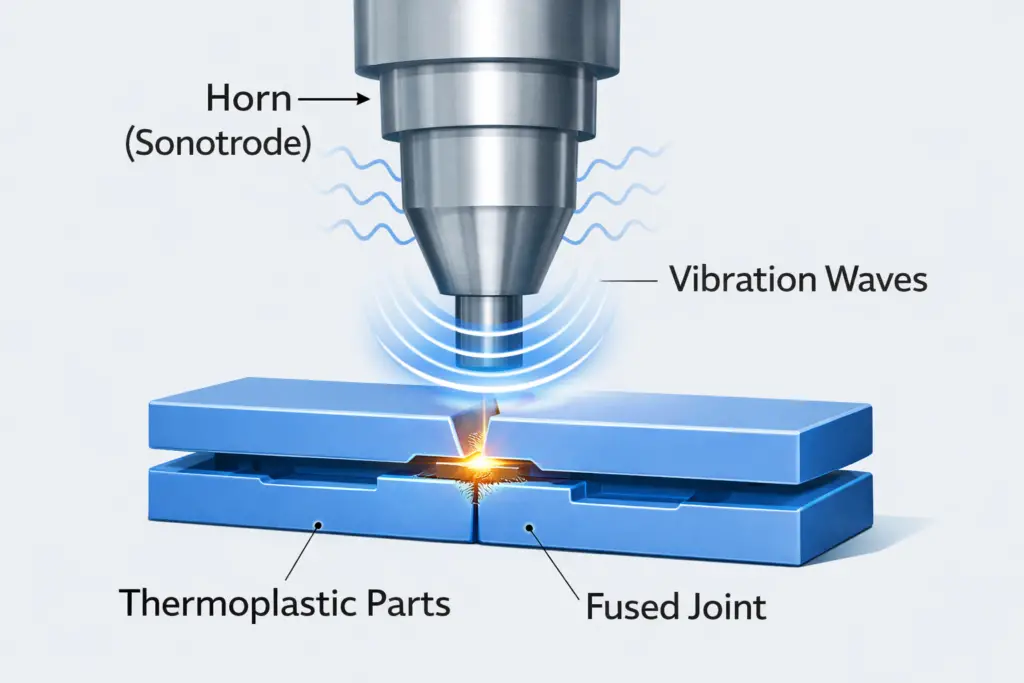
What Is Ultrasonic Welding of Plastics?
Ultrasonic welding is a solid-state joining process where high-frequency mechanical vibrations (typically 20–40 kHz) are applied to thermoplastic parts under pressure. These vibrations generate localized heat at the joint interface, causing the plastic to melt and fuse.
Why Ultrasonic Welding Is Preferred
- No adhesives or fasteners required
- Very short cycle times (milliseconds)
- Clean and repeatable process
- Excellent for mass production
Importance of Component Design in Ultrasonic Welding
Even the best ultrasonic welding machine cannot compensate for poor part design. Component geometry controls:
- Where heat is generated
- How melt flows
- Weld strength and appearance
Poor design leads to weak welds, excessive flash, or cosmetic defects.

Energy Director (Projection) Joint Design
The energy director is the most common joint design in ultrasonic welding. It is a small triangular ridge molded into one of the mating surfaces.
How It Works
Energy Director Shape Based on Plastic Type
Different plastics behave differently under ultrasonic vibration.
| Plastic Type | Recommended Energy Director |
|---|---|
| Amorphous (ABS, PC) | Right-angle triangle |
| Semi-crystalline (PP, Nylon) | Equilateral triangle |
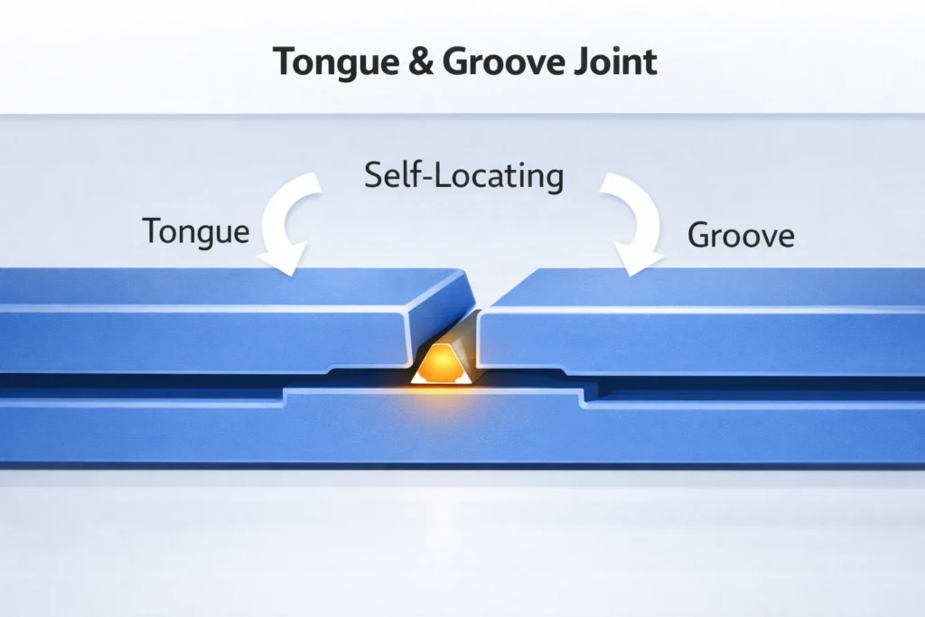
Tongue and Groove Joint Design
A tongue and groove joint is a variation of the energy director design. It improves part alignment and hides weld flash.
Advantages
- Self-locating during assembly
- Better cosmetic appearance
- Controlled melt flow
Limitations
- Slightly lower weld strength than shear joints
- Requires precise molding tolerances
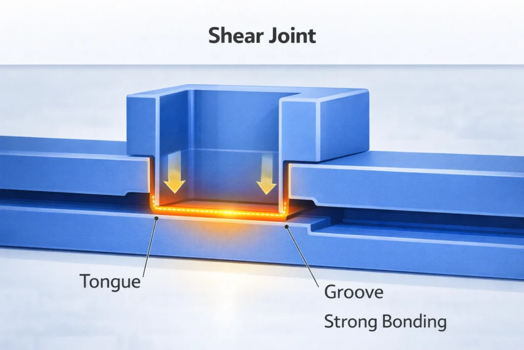
Shear Joint Design (High-Strength Applications)
Shear joints are used where maximum weld strength and hermetic sealing are required.
How Shear Joints Work
- One part telescopes into another
- Melting occurs along vertical walls
- Produces strong, uniform bonds
Typical Applications
- Medical containers
- Fluid reservoirs
- Automotive housings
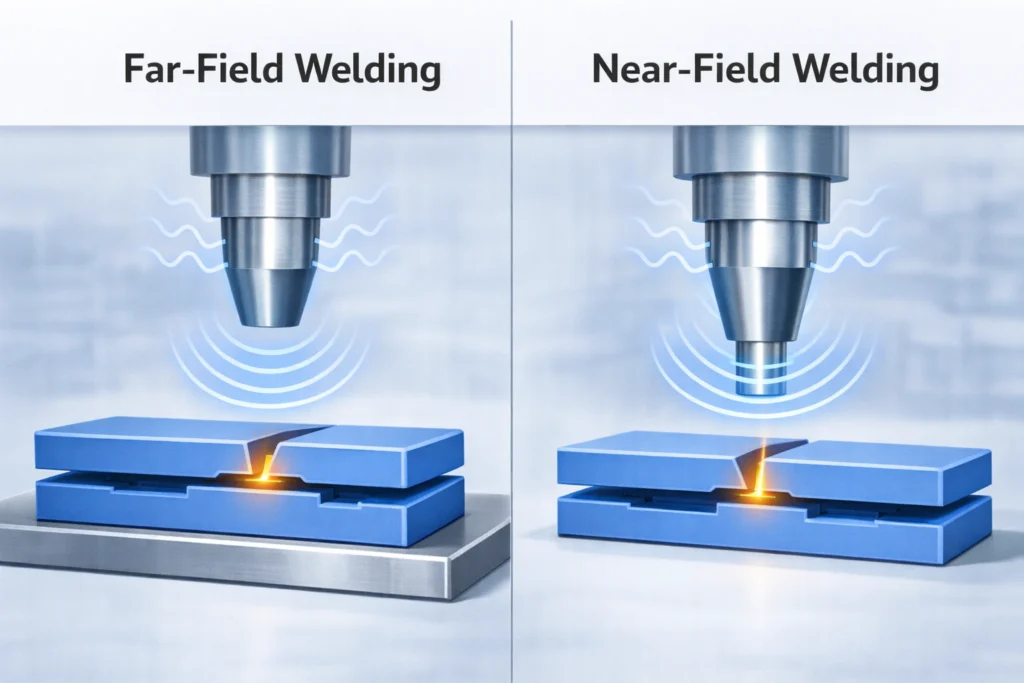
Near-Field vs Far-Field Ultrasonic Welding
Joint location relative to the ultrasonic horn greatly affects weld quality.
Near-Field Welding
- Joint is close to the horn
- Better energy transfer
- Preferred for thick or stiff parts
Far-Field Welding
- Joint is farther from the horn
- Energy must travel through the part
- Requires careful parameter control
Avoid Sharp Corners – Use Radii
Sharp corners create stress concentrations and interfere with vibration transmission.
Design Best Practice
- Use smooth radii at corners
- Avoid sudden thickness changes
- Improve weld consistency
Key Ultrasonic Welding Parameters
Proper parameters are as important as joint design.
1. Amplitude
- Controls vibration intensity
- Higher amplitude → more heat generation
- Semi-crystalline plastics require higher amplitude
Effect of Amplitude on Melt Zone
Incorrect amplitude can cause:
- Insufficient melting (low amplitude)
- Excessive flash or part damage (high amplitude)
2. Trigger Pressure
- Pressure at which ultrasonic vibration starts
- Ensures proper part contact before welding
3. Weld Time
- Duration of ultrasonic vibration
- Too short → weak weld
- Too long → material degradation
4. Hold Time
- Time pressure is maintained after vibration stops
- Allows molten plastic to solidify
Practical Ultrasonic Welding Design Checklist
Before finalizing a plastic part for ultrasonic welding, confirm:
- ✔ Correct joint design
- ✔ Compatible material selection
- ✔ Optimized welding parameters
- ✔ Proper joint location
- ✔ Suitable horn proximity
Conclusion
Ultrasonic welding of injection-moulded components is a highly reliable and economical process—but only when component design and weld parameters work together.
By:
- Selecting the right joint design
- Avoiding poor geometries
- Optimizing amplitude, pressure, and time
manufacturers can achieve strong, repeatable, and visually clean welds suitable for high-volume production.