Carbon Equivalent (CE) in Welding Metallurgy — Calculator & Complete Guide
The Carbon Equivalent (CE) is the single most important calculated value in welding metallurgy. Rather than assessing carbon content alone, CE combines the contributions of all major alloying elements — manganese, chromium, molybdenum, vanadium, nickel, and copper — into one number that accurately predicts how a steel will behave during welding. It quantifies hardenability: how readily the heat-affected zone (HAZ) will form hard martensite, and how susceptible the joint will be to hydrogen-induced cold cracking (HICC).
Engineers and welding inspectors use CE to make three critical decisions before any production welding begins: whether preheating is required, what preheat temperature to specify, and whether post-weld heat treatment (PWHT) will be needed. Getting these decisions wrong leads directly to weld joint failure, project delays, and costly repairs. This guide explains both the IIW formula and the Pcm (Ito-Bessyo) formula, provides a live calculator, and covers every practical consideration for applying CE in fabrication and construction.
Carbon Equivalent Calculator
Enter the steel chemical composition from the Material Test Certificate (MTC). Switch between the IIW formula and the Pcm (Ito-Bessyo) formula using the tabs below.
Why Carbon Equivalent Matters in Welding
When a weld is deposited, the steel immediately surrounding the fusion zone is heated rapidly and then cooled at rates determined by the heat input, preheat temperature, and section thickness. If this cooling is fast enough, the microstructure transforms into martensite — a hard, brittle phase that is highly susceptible to cracking when hydrogen is present. The CE value tells you, before you strike an arc, how likely this is to happen and what preventive measures are needed.
CE is used at every stage of a project: during material procurement to screen incoming steel, during procedure qualification to establish preheat and interpass temperature requirements, and during production welding as a daily quality check. For sour service applications, CE control is also critical for meeting the HAZ hardness limits of NACE MR0175/ISO 15156.
The Two Carbon Equivalent Formulas — Explained
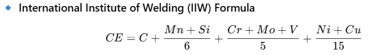
IIW Formula (International Institute of Welding)
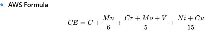
The IIW formula is the most globally recognised CE formula and is used in the majority of structural steel, pressure vessel, and piping codes. It was developed for steels with carbon content above 0.18% and gives equal weight to the hardenability contributions of Cr, Mo, and V in one group, and Ni and Cu in another.
Pcm Formula (Ito-Bessyo / Japanese Industrial Standard)
The Pcm formula (also written Ceq or CEIIW in some sources) was developed by Ito and Bessyo specifically for low-carbon, high-strength low-alloy (HSLA) steels with carbon content below 0.18%. It accounts for the especially large effect of boron and gives a more accurate cracking risk assessment for modern fine-grain structural steels used in shipbuilding, offshore, and heavy fabrication.
Which Formula to Use?
| Criterion | IIW Formula | Pcm Formula |
|---|---|---|
| Carbon content | >0.18 wt% | <0.18 wt% |
| Steel type | Carbon steel, low-alloy, pressure vessel | HSLA, fine-grain, offshore structural |
| Boron effect | Not specifically accounted for | Explicitly included (5B term) |
| Referenced by | AWS D1.1, ASME, BS EN 1011-2, ISO 17671 | JIS Z 3158, DNV, offshore codes |
| Typical CE threshold (no preheat) | <0.40% | <0.25% |
Understanding Hardenability and the HAZ
When the welding arc passes over steel, the base material adjacent to the fusion line is heated to temperatures above the upper critical temperature (Ac3), fully austenitising the microstructure. As the weld progresses and the arc moves away, this zone cools. The cooling rate and the steel’s hardenability (quantified by CE) together determine what microstructure forms.
Effect of Each Alloying Element on CE and Weldability
| Element | Symbol | IIW Divisor | Pcm Divisor | Primary Effect on Weldability |
|---|---|---|---|---|
| Carbon | C | 1 (direct) | 1 (direct) | Strongest hardenability agent. Directly raises HAZ hardness, martensite potential, and hydrogen cracking susceptibility. |
| Manganese | Mn | 6 | 20 | Deoxidiser and strengthener. Raises hardenability significantly; combined with Ni also lowers Ac1 in CSEF steels like Grade P91. |
| Chromium | Cr | 5 | 20 | Increases hardenability and oxidation resistance. Contributes to M23C6 carbide formation in high-Cr steels, delaying softening at high temperature. |
| Molybdenum | Mo | 5 | 15 | Strong hardenability agent and solid-solution strengthener. Retards temper embrittlement and coarsening of carbides in high-temperature service. |
| Vanadium | V | 5 | 10 | Fine carbide/nitride former. Grain refiner. Moderate hardenability effect but critical for creep strength in CSEF steels. |
| Nickel | Ni | 15 | 60 | Improves toughness and hardenability. Lower hardenability contribution than C or Mn. In sour service steels, limited to 1% to avoid SSC susceptibility. |
| Copper | Cu | 15 | 20 | Improves corrosion resistance (weathering steels). Low hardenability contribution but can cause hot cracking if Cu >0.3% without Ni balancing. |
| Silicon | Si | Not in IIW | 30 | Deoxidiser. Moderate hardenability effect. Present in Pcm because HSLA steels often use Si for strength; IIW excludes it as contribution is minor at typical Si levels. |
| Boron | B | Not in IIW | x5 (potent) | Extremely potent hardenability agent even at trace levels (0.001%). The 5B term in Pcm reflects this outsized effect. Critical for HSLA, linepipe, and offshore steels. |
Weldability Thresholds and Preheat Requirements
The following table summarises the generally accepted weldability classifications based on IIW CE values. Note that preheat requirements are also influenced by section thickness, heat input, hydrogen content of the consumable, and restraint level — CE alone does not determine preheat. Always refer to the applicable welding code or procedure for your specific combination of factors.
| CE Value (IIW) | Weldability Rating | Typical Preheat | Controls Required |
|---|---|---|---|
| <0.40% | Excellent | None (thin sections) | No special controls needed for standard conditions. Low-hydrogen electrodes still recommended for thick sections. |
| 0.40 — 0.45% | Good | None to 75 deg C | Monitor heat input. Preheat thicker sections (>20 mm). Use low-hydrogen electrodes (<5 ml/100g). |
| 0.45 — 0.50% | Caution | 75 — 150 deg C | Preheat mandatory. Control heat input. Low-hydrogen electrodes essential. Consider H2 baking. |
| 0.50 — 0.60% | High Risk | 150 — 250 deg C | High preheat. Strict interpass temperature control. PWHT likely required. 100% NDE recommended. |
| >0.60% | Very High Risk | >250 deg C | Maximum preheat. PWHT mandatory. Hydrogen bake-out between passes. Consult metallurgist. |
Worked Calculation Example
Consider an API 5L Grade X60 linepipe steel with the following certified chemical composition from the MTC:
| Element | C | Mn | Cr | Mo | V | Ni | Cu | Si | B |
|---|---|---|---|---|---|---|---|---|---|
| Composition (wt%) | 0.16 | 1.42 | 0.12 | 0.05 | 0.05 | 0.15 | 0.18 | 0.28 | 0.0002 |
IIW Calculation
Pcm Calculation (for the same steel)
Practical Engineering Notes for CE Application
Reading CE from Material Test Certificates
The chemical composition for CE calculation must always come from the certified Material Test Certificate (MTC) — specifically the heat analysis or product analysis values. Nominal or minimum values from the material standard are not sufficient for accurate CE determination. For guidance on reading MTCs, including identifying which analysis to use, refer to our dedicated MTC guide.
CE and Hydrogen Level
CE predicts susceptibility — but the actual cracking risk also depends on the diffusible hydrogen content (H) of the weld deposit. A steel with CE 0.45% welded with a very low-hydrogen process (GTAW, H <1 ml/100g) may need no preheat, while the same steel welded with a rutile electrode (H up to 15 ml/100g) could require significant preheat. BS EN 1011-2 combines CE with hydrogen level and combined thickness to determine preheat in a more rigorous method than CE alone.
Preheat Temperature Maintenance
Specifying the correct preheat temperature is only half the task — the preheat must be measured and maintained throughout welding. Verification tools include contact pyrometers, temperature-indicating crayons (Tempilstik), and infrared thermometers. For critical applications, thermocouple-based monitoring with continuous recording is required. See our P91 welding guide for an example of rigorous preheat monitoring requirements in high-specification fabrication.
CE and PWHT Decisions
Post-weld heat treatment (PWHT) is used to relieve residual stresses, temper hard martensite, and facilitate hydrogen escape from the joint. For steels above CE 0.50%, PWHT is typically mandatory under major construction codes. The PWHT temperature for carbon and low-alloy steels is generally 595–720 deg C, held for 1 hour per 25 mm of thickness. For the relationship between CE, Mn+Ni content, and the PWHT window in CSEF steels, see our guide on Ni+Mn restrictions in P91 and P92.
CE in Sour Service
In H2S-containing (sour service) environments, controlling CE is critical not just for avoiding cold cracking during fabrication, but for keeping HAZ hardness within the 250 HV10 maximum required by NACE MR0175/ISO 15156. Higher CE steels are more hardenable and produce harder HAZ zones that are more susceptible to sulphide stress cracking (SSC). See our complete sour service guide and nickel restriction in sour service articles for the full picture.
Strategies for Welding High-CE Steels
When materials with CE above 0.45% must be welded, the following controls reduce cracking risk and ensure acceptable joint properties:
1. Preheating
The single most effective intervention. Preheating slows the cooling rate through the transformation range, reducing martensite formation and giving hydrogen more time to escape. Preheat should be applied to the full joint thickness, extending at least 75 mm on each side of the weld preparation. Interpass temperature (minimum = preheat, maximum per the WPS) must be maintained throughout multi-pass welding.
2. Low-Hydrogen Welding Consumables
Hydrogen-induced cracking requires both a hard microstructure and a source of hydrogen. Using E7018 SMAW electrodes (low-hydrogen, moisture-resistant) or GTAW/GMAW processes eliminates the hydrogen source. Electrodes must be stored and handled per manufacturer requirements — even low-hydrogen electrodes absorb moisture if improperly stored. See our consumable nomenclature guide for electrode classification details.
3. Controlled Heat Input
Low heat input produces faster cooling, increasing martensite formation. High heat input causes grain coarsening and reduced toughness. The target heat input for most high-CE steels is 1.0 to 3.0 kJ/mm. Both extremes must be avoided. The minimum heat input is implicitly set by the preheat requirement.
4. Hydrogen Baking and PWHT
For highly restrained joints or very high CE steels, applying a post-weld hydrogen bake-out (at 150-250 deg C for 1-4 hours, immediately after welding and before cooling) accelerates hydrogen diffusion from the joint. PWHT then tempers the HAZ and relieves residual stress, restoring toughness and reducing cracking risk.
Recommended Books on Welding Metallurgy and CE
Deepen your understanding of carbon equivalent, weldability, and HAZ metallurgy with these authoritative references, available on Amazon India.
Disclosure: WeldFabWorld participates in the Amazon Associates programme (StoreID: neha0fe8-21). If you purchase through these links, we may earn a small commission at no extra cost to you. This helps support free technical content on this site.
Frequently Asked Questions
What is Carbon Equivalent (CE) in welding?
Carbon Equivalent (CE) is a calculated value that combines carbon content with other alloying elements (Mn, Cr, Mo, V, Ni, Cu) into a single number that predicts steel weldability and susceptibility to heat-affected zone cracking. The higher the CE, the harder the HAZ and the greater the risk of hydrogen-induced cold cracking (HICC). CE is the starting point for determining whether preheating, controlled cooling, or post-weld heat treatment is required.
What is the difference between the IIW formula and the Pcm formula?
The IIW formula (CE = C + Mn/6 + (Cr+Mo+V)/5 + (Ni+Cu)/15) is best suited for steels with carbon above 0.18% and is used in AWS D1.1, ASME, and BS EN 1011-2. The Pcm formula (Pcm = C + Si/30 + (Mn+Cu+Cr)/20 + Ni/60 + Mo/15 + V/10 + 5B) is better suited for low-carbon HSLA steels below 0.18% C, as it explicitly accounts for silicon and boron. For most structural carbon steels, IIW is the default. For modern high-strength linepipe or offshore structural steels, Pcm is often more appropriate and gives a more accurate cracking risk assessment.
What CE value requires preheating before welding?
As a general guideline using the IIW formula: CE below 0.40% usually requires no preheat; CE 0.40-0.45% needs careful monitoring and preheat for thicker sections; CE 0.45-0.50% requires preheat (typically 75-150 deg C); CE 0.50-0.60% requires preheat (150-250 deg C) and likely PWHT; CE above 0.60% demands maximum preheat, PWHT, and strict inspection. These thresholds also depend on section thickness, heat input, and hydrogen level — always verify against the applicable welding code or procedure specification.
Where do I find the chemical composition to calculate CE?
The chemical composition is found on the Material Test Certificate (MTC), also called a Mill Certificate or Test Report. This document accompanies every steel product and lists the certified chemical analysis for each heat. Always use the MTC values rather than nominal composition from product standards, as actual values can vary within the specification range and significantly affect the CE result. Our MTC reading guide explains how to interpret every field on a material certificate.
Can CE predict all weld cracking risks?
CE is an excellent predictor of hydrogen-induced cold cracking (HICC) in the HAZ, but it does not capture all cracking mechanisms. It does not directly predict solidification (hot) cracking, lamellar tearing, stress corrosion cracking, or sensitisation-related weld decay in stainless steels. CE should always be used alongside other assessments including diffusible hydrogen content, restraint level, and heat input for a complete cracking risk evaluation.
How does plate thickness affect the preheat requirement for a given CE?
Thicker sections cool faster, increasing the HAZ cooling rate and martensite formation risk. For the same CE value, thicker plates require higher preheat. Standards such as BS EN 1011-2 use combined thickness (sum of both plate thicknesses at the joint) to determine preheat alongside CE. A steel with CE 0.42% may need no preheat at 10 mm but require 75 deg C preheat at 30 mm thickness. The heat input also modifies this — lower heat input (faster cooling) effectively requires higher preheat for a given CE and thickness combination.
What is the relationship between CE and HAZ hardness in sour service?
CE is directly related to hardenability — how easily martensite forms in the HAZ. Higher CE steels form more martensite, producing higher HAZ hardness values. In sour service applications (wet H2S environments), NACE MR0175/ISO 15156 limits HAZ hardness to 250 HV10 maximum to prevent sulphide stress cracking. CE control, minimum preheat, and PWHT are the primary methods for keeping HAZ hardness within these limits. For carbon steels in sour service, a CE below 0.43% combined with correct preheat and PWHT is typically needed to achieve 250 HV10 compliance.
What is ‘B’ (boron) in the Pcm formula and why is it multiplied by 5?
Boron (B) is an extremely potent hardenability agent even at trace concentrations (typically 0.001-0.003%). In the Pcm formula, boron is multiplied by 5 to reflect its outsized effect on HAZ hardenability relative to its concentration. A boron content of 0.002% adds 0.01 to Pcm — the same as 0.01% more carbon. Boron-treated steels therefore require careful preheat assessment using the Pcm formula, and the MTC must always be checked for boron content. If the MTC does not list boron, assume it is 0 for calculation purposes.