In Engineering, Procurement, and Construction (EPC) projects, protective coatings play a vital role in safeguarding steel structures, pipelines, storage tanks, offshore platforms, and heavy equipment against corrosion and environmental degradation. One of the most critical quality checks in coating inspection is Dry Film Thickness (DFT) testing.
DFT testing ensures that the applied coating has the correct thickness after curing. This single test influences corrosion resistance, coating durability, and the overall lifecycle cost of an asset.
What is Dry Film Thickness (DFT)?
- DFT is the thickness of a fully cured (dried) coating film applied to a substrate.
- It is typically measured in microns (µm) or mils.
- DFT is measured non-destructively using calibrated instruments.
- It is one of the most important quality control parameters in any protective painting or coating system.
Simply put, if the applied coating is too thin, it may fail to protect the substrate. If it is too thick, it may lead to cracking, solvent entrapment, blistering, or early failure.

Why DFT Testing is Crucial
- Low DFT Issues:
- Inadequate corrosion resistance
- Reduced service life of the coated asset
- Risk of early coating breakdown
- High DFT Issues:
- Cracking and wrinkling of the paint film
- Increased chances of delamination or blistering
- Excessive material usage and wastage, raising project costs
- Long-Term Asset Protection:
Correct DFT ensures structural steel, pipelines, tanks, and other equipment are protected for years against environmental and operational stresses. - Quality Assurance & Control:
DFT measurement forms an essential hold point in Inspection Test Plans (ITPs) and QA/QC documentation. It is also part of final inspection and acceptance before project handover.
Applicable International Standards
Several international standards govern DFT measurement methods, acceptance criteria, and reporting:
- ISO 19840: Defines how to measure and accept DFT for corrosion protection.
- ISO 2808: Provides methods for determining film thickness (destructive and non-destructive).
- SSPC-PA 2: Guidelines for using magnetic gauges to measure DFT on ferrous substrates.
- ASTM D7091: Procedure for non-destructive DFT measurement on both ferrous and non-ferrous substrates.
- ISO 2178 & ISO 2360: Specific methods using magnetic induction and eddy current principles.
These standards ensure uniformity and reliability of inspection across global projects.
Instruments Used for DFT Testing
- Type 1 – Magnetic Pull-Off Gauges
- Example: Elcometer 211
- Operates manually using attraction between a magnet and steel
- Simple, rugged, low-cost but less precise
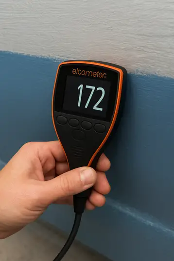
- Type 2 – Electronic / Digital Gauges
- Examples: Elcometer 456, Defelsko PosiTector
- Uses magnetic induction (ferrous substrates) and eddy current (non-ferrous substrates)
- Provides quick, accurate, repeatable readings
- Many models include data logging and reporting features
- Other Methods (less common in EPC projects)
- Destructive testing (ISO 2808): Cutting a V-notch and measuring microscopically.
- Used rarely, only when highly precise confirmation is needed.

Calibration & Verification
- Instruments must be calibrated in accordance with ISO/ASTM requirements.
- Zero setting must be performed on an uncoated substrate (bare steel or aluminum).
- Calibration should be traceable to national/international standards.
- Verification is required before, during, and after inspection shifts.
- Inspectors should maintain calibration certificates and verification records.
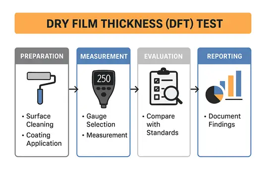
Testing Procedure
- Preparation
- Ensure the coating is fully cured as per manufacturer’s data sheet.
- Clean the substrate of dust, oil, grease, and salts.
- Select the correct probe depending on whether the substrate is ferrous or non-ferrous.
- Measurement
- Place the probe perpendicular to the coated surface.
- Take spot readings as per specification:
- SSPC-PA 2 → 5 spots per 10 m² of coated area
- Each spot = average of 3 readings within a 38 mm (1.5-inch) circle
- Avoid edges, corners, weld seams unless specifically instructed.
- Recording
- Record each reading and calculate averages.
- Compare with minimum and maximum acceptable values.
- Highlight any areas outside tolerance and take corrective action.
Acceptance Criteria
- ISO 19840
- Mean of readings = Nominal DFT
- Individual readings may be lower, but not more than 20% below nominal
- Not more than 20% of readings may fall below nominal
- SSPC-PA 2
- Average of 3 readings = 80–120% of specified DFT
- No individual reading less than 80% or more than 150% (unless otherwise specified)
- Client Specifications
- Many oil & gas companies (e.g., ARAMCO, ADNOC, EIL) impose stricter tolerances, often ±25 µm.
Typical DFT Ranges
- Primer coat: 50–75 µm
- Intermediate coat: 100–150 µm
- Finish coat: 50–75 µm
- Total DFT: 200–300 µm (depending on PDS & client specification)
Practical Considerations
- Avoid measuring on edges, corners, welds unless specified.
- If DFT is too low, apply additional coats.
- If DFT is too high, corrective methods such as sanding or blasting may be needed.
- Check environmental factors (temperature, humidity, dew point) before measurement.
- Use Wet Film Thickness (WFT) checks during application to predict final DFT.
- DFT should be checked after each coat to avoid excessive build-up.
Reporting & Documentation
A standard DFT inspection report should include:
- Project name, location, and component details
- Surface preparation details (abrasive blasting, cleanliness, roughness profile)
- Coating system (manufacturer, product, number of coats, curing time)
- DFT readings (individual, averages, grid reference)
- Instrument details (model, serial number, calibration data)
- Pass/fail evaluation against specification
- Inspector’s details and signatures
DFT results are recorded in Quality Control dossiers and often form part of project completion certificates.
Why DFT Testing Matters
Proper DFT testing is not just a routine inspection—it directly impacts:
- Corrosion resistance & structural integrity
- Project lifecycle cost and maintenance
- Client satisfaction & regulatory compliance
- Safety and reliability of critical infrastructure
In EPC projects, where assets are expected to perform reliably for decades, ensuring accurate DFT is a non-negotiable requirement.
✅ Pro Tip: Use modern digital gauges with data logging for large projects. They streamline reporting, reduce errors, and ensure full traceability.
By integrating DFT testing as a strict QA/QC checkpoint, EPC projects can achieve higher reliability, reduced failures, and longer-lasting protection for valuable infrastructure.
FAQs (for Featured Snippets)
Q1. What is Dry Film Thickness (DFT) in coating inspection?
A: DFT is the thickness of a fully cured paint or coating film measured in microns (µm) or mils. It ensures compliance with project specifications and corrosion protection requirements.
Q2. Why is DFT testing important in EPC projects?
A: It ensures proper corrosion resistance, prevents coating failures, avoids excess material wastage, and forms a key quality checkpoint in Inspection Test Plans (ITP).
Q3. Which instruments are used for DFT measurement?
A: Magnetic pull-off gauges (Elcometer 211) and electronic gauges (Elcometer 456, Defelsko PosiTector) using magnetic induction or eddy current principles.
Q4. What are typical DFT ranges for coating systems?
A: Primer: 50–75 µm, Intermediate: 100–150 µm, Finish: 50–75 µm, with a total DFT of 200–300 µm depending on client specification.
Q5. What are the acceptance criteria for DFT testing?
A: As per ISO 19840, average readings must meet nominal DFT, with individual readings not more than 20% below. SSPC-PA 2 requires 80–120% of specified thickness.
