Design and Inspection Guide to Minimum Weld Spacing
Minimum weld spacing — the required distance between adjacent weld joints — is one of the most practically important yet frequently misunderstood requirements in pressure vessel, piping, and structural fabrication. In regulated industries, getting this wrong does not mean a minor non-conformance: overlapping heat-affected zones, obstructed NDT access, uneven PWHT response, and compounded residual stress concentrations are all direct consequences of welds placed too close together, and any one of them can drive costly weld removal, joint redesign, or — in the worst case — in-service failure. Every major fabrication code addresses weld spacing, but the rules vary significantly between ASME, API, BS, ISO, and operator-specific specifications, which creates real confusion on multi-standard projects.
This guide covers the technical reasons why weld spacing matters at the metallurgical level, consolidates the spacing requirements from all major codes and operator standards into a single reference table, introduces a worked calculation approach for common configurations, and provides practical inspection guidance for verifying compliance in fabrication and field situations. A free weld spacing checker calculator is included immediately below to help you determine the minimum required distance for any thickness and code combination.
Weld Spacing Minimum Calculator
Enter the base material thickness and select the applicable code. The calculator returns the minimum weld-to-weld spacing for the selected configuration.
Why Minimum Weld Spacing Is a Structural Requirement
The requirement for minimum weld spacing is rooted in welding metallurgy, not administrative preference. Every weld produces a heat-affected zone (HAZ) — a band of base metal that has been exposed to elevated temperatures (typically 500–1350°C) during the thermal cycle of welding, but has not been melted. Within the HAZ, multiple metallurgical changes occur simultaneously:
- Grain coarsening in the region closest to the fusion boundary (coarse-grain HAZ), reducing fracture toughness at low temperatures.
- Partial re-austenitisation in regions heated to the AC1–AC3 temperature range, producing a heterogeneous microstructure with variable hardness.
- Carbide precipitation and sensitisation in austenitic stainless steels heated to 550–850°C — the cause of stainless steel weld decay.
- Residual tensile stress across the full HAZ width, from the weld centreline to the outer HAZ boundary, due to non-uniform thermal contraction during cooling.
- Hydrogen entrapment in the HAZ during cooling, contributing to hydrogen-induced cold cracking (HICC) in hardenable steels if preheat is insufficient.
When a second weld is deposited too close to an existing one, its own thermal cycle reheats the HAZ of the first weld. This superimposed reheating — sometimes called double thermal cycling — causes additional grain growth in the coarse-grain region and may precipitate intermetallic phases (sigma in duplex stainless, carbides in chrome-moly steels) that the original welding procedure was designed to avoid. The combined HAZ region is larger, harder, and more prone to cracking than either individual HAZ, and it occupies a location that is under combined residual stress from both weld deposits.
Effect on Non-Destructive Testing Access
The physical obstruction of NDT probes by closely spaced welds is as important as the metallurgical concern. For radiographic testing (RT), the radiograph of two overlapping welds will show the superimposed images of both weld cross-sections — masking any indication that falls in the overlap zone. For ultrasonic testing (UT), the transducer requires a clear scan zone of at least 1.5 times the probe standoff distance on both sides of the weld centreline. When a second weld falls within this zone, part of the first weld’s volume cannot be examined. Phased array UT (PAUT) has similar aperture requirements. The practical result is that closely spaced welds create uninspectable zones that cannot be accepted without formal concession and engineering fitness-for-service justification.
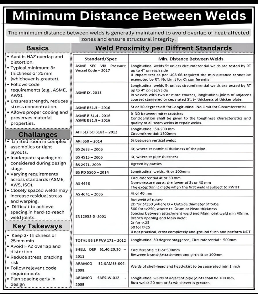
Minimum Weld Spacing — Code and Standard Requirements
The following table consolidates the minimum weld spacing requirements from the major fabrication codes and operator specifications. All distances are measured weld toe to weld toe unless specified otherwise. Where the requirement is expressed as a multiple of thickness (t), use the nominal thickness of the thicker material at the joint.
| Standard / Specification | Type | Weld Configuration | Minimum Spacing Requirement | Key Notes |
|---|---|---|---|---|
| ASME Section VIII Div. 1 | Pressure Vessel | Longitudinal seams (adjacent courses) | 3t or 50 mm (2 in), whichever is greater | RT examination may substitute for offset requirement unless UCS-66 impact testing applies — then physical spacing is mandatory |
| ASME Section VIII Div. 1 | Pressure Vessel | Nozzle attachment weld to main seam | Per project spec; typically 50 mm min or 3t | Ensure full RT/UT coverage of both nozzle weld and adjacent seam is achievable |
| ASME B31.3 (Para. 328.5.1) | Process Piping | Longitudinal seams of adjacent pipe sections | 30° angular offset (for wall t > 19 mm) | Prevents seam alignment in same axial plane; less restrictive than absolute distance |
| ASME B31.4 / B31.8 | Pipeline | Miter crotch to weld | 5 × nominal OD from miter crotch | Material toughness must be considered for repair welds in close proximity to girth welds |
| API 5L / ISO 3183 | Line Pipe | Longitudinal seam | 50–200 mm (varies by pipe diameter) | Seams of adjacent pipe sections in a spool must be offset by this distance around the circumference |
| API 5L / ISO 3183 | Line Pipe | Circumferential (girth) welds | 1500 mm minimum between girth welds | Applies to long-seam pipe; prevents short pup-piece insertions that create back-to-back circumferential welds |
| API 650 (10th Edition+) | Tank | Vertical (longitudinal) seams in adjacent shell courses | 5t (five times shell plate thickness) | T-intersections between vertical and horizontal seams are not permitted in the main shell |
| BS 2633:2006 | Pipe Welding | Toe-to-toe between adjacent welds | 4 × nominal pipe wall thickness | Applies to ferritic and austenitic pipe welds under BS standard |
| BS 4515:2006 | Pipeline | Toe-to-toe between welds | 4 × pipe wall thickness | Consistent with BS 2633; applies to field pipeline welding |
| PD 5500:2024 | Pressure Vessel | Longitudinal seam (adjacent courses) | 4t or 100 mm, whichever is greater | Stricter than ASME; the 100 mm minimum is a firm lower bound regardless of thickness |
| EN 12952-5 | Boiler | Tube seam welds (< 25 mm wall) | 20t minimum | For thicker tubes (> 250 mm wall), up to 500t may apply — consult standard directly |
| AS 4041:2006 | Piping (Australia) | General weld-to-weld | 4t or 40 mm, whichever is greater | Applicable to pressure piping in Australian jurisdictions |
| AS 4458 | Pressure Vessel (Aus) | Circumferential welds | 4t or 30 mm, whichever is greater | Non-pressure part welds: lower of 3t or 40 mm |
| TOTAL GS EP PVV 171 | Operator Spec | Longitudinal seam | 30° stagger minimum | Circumferential welds: 500 mm minimum between girth welds |
| SHELL DEP 61.40.20.30 | Operator Spec | Circumferential welds | 1D (one pipe OD) or 500 mm, whichever is greater | Branch-to-girth seam: 4t or 100 mm; stricter than most construction codes |
| ARAMCO SAES-W-012 | Operator Spec | Longitudinal seams (adjacent pipe joints) | 100 mm minimum | Butt welds to any other weld: 20 mm or 3t minimum; shell-head to head-skirt welds: 25 mm (1 in) minimum separation |
| BS 2971:2009 | Pipe Welding | All weld configurations | By agreement between parties | No fixed minimum; engineer must specify and document agreed spacing in the design package |
How to Calculate Minimum Weld Spacing — Worked Examples
The most common weld spacing calculation converts a thickness-based requirement (expressed as a multiple of t) into an actual millimetre dimension. The following worked examples cover the three most frequently encountered configurations in pressure vessel and piping fabrication.
Where n = code multiplier (3, 4, or 5 depending on code)
t = nominal wall thickness of the thicker plate (mm)
fixed_minimum = code-specified absolute minimum (mm)
Example 1 — ASME Sec VIII Div. 1, Carbon Steel Vessel Shell:
Shell wall thickness t = 18 mm
Minimum seam offset = MAX(3 × 18, 50) = MAX(54, 50) = 54 mm
Required spacing = 54 mm (3t governs)
Example 2 — PD 5500, Pressure Vessel Shell:
Shell wall thickness t = 12 mm
Minimum seam offset = MAX(4 × 12, 100) = MAX(48, 100) = 100 mm
Required spacing = 100 mm (fixed minimum governs)
Example 3 — API 650 Storage Tank, t = 14 mm:
Adjacent vertical shell seam offset
Minimum spacing = 5 × 14 = 70 mm
Required spacing = 70 mm
Example 4 — SHELL DEP, 12″ pipe (OD = 323.9 mm), Circumferential:
Minimum spacing = MAX(1 × 323.9, 500) = MAX(323.9, 500) = 500 mm
Required spacing = 500 mm (fixed minimum governs)
Material-Specific Weld Spacing Guidance
The minimum code spacing is a lower bound. For materials with elevated HAZ sensitivity, engineering best practice — and often project specifications — requires greater spacing than the code minimum. The following guidance consolidates the practical engineering considerations by material class.
| Material Class | HAZ Sensitivity | Recommended Min. Spacing | Primary Concern | Additional Requirement |
|---|---|---|---|---|
| Carbon steel (P1), low-strength | Low–Moderate | 3t or 50 mm (ASME), or per code | HAZ grain coarsening; hydrogen cracking if preheat insufficient | Preheat verification; CE check via carbon equivalent calculator |
| Carbon-manganese steel, medium strength | Moderate | 4t or 50 mm minimum | HAZ hardness; hydrogen cracking; PWHT coverage | Minimum preheat 100°C; verify PWHT soak band covers both welds |
| P4 / P5 Chrome-Moly (P91, P22) | High | 5t or 100 mm minimum; engineering review for < 150 mm | Type IV cracking in inter-critical HAZ; PWHT thermal gradient; hydrogen cracking | Strict heat input control; thermocouple placement ensures both welds reach soak temp; creep interaction in service |
| Austenitic stainless (P8) | Moderate | 3t or 50 mm; 75 mm preferred for sensitisation-sensitive service | Sensitisation and weld decay in double-cycled HAZ; delta ferrite modification | Consider solution annealing if double thermal cycle cannot be avoided; use low-carbon grades (304L, 316L) |
| Duplex stainless (P10H) | High | 5t or 100 mm minimum | Sigma phase precipitation in double-cycled HAZ; ferrite imbalance; PREN degradation | No PWHT; strict interpass temperature control on both welds; ferrite measurement on each pass |
| High-strength / QT steels (> 550 MPa) | High | 40 mm or 4t minimum; 5t preferred | HAZ softening (over-tempering of quench-tempered zone); hydrogen cracking; hardness exceedance | Low hydrogen process; maintain preheat between welds; consider post-weld HICC bake-out |
| Nickel alloys (P43, P45) | High | 5t or 100 mm minimum; supplier guidance | Hot cracking; intermetallic precipitation; HAZ sensitisation | Strict heat input limits; qualified welder with nickel alloy experience; NDT coverage verification |
Practical Challenges in Maintaining Weld Spacing
Code compliance with weld spacing requirements is straightforward when addressed at the design stage. The problems arise when spacing is not considered during layout, or when field conditions impose constraints that were not anticipated. The following scenarios represent the most common real-world challenges.
1. Short Pup Pieces and Back-to-Back Circumferential Welds
In piping fabrication, it is common to insert short pup pieces (cut-to-length pipe sections) to achieve the correct spool length. If the pup piece is too short, the two circumferential welds at each end may be closer than the specified minimum. API 5L requires 1500 mm between girth welds; SHELL DEP requires the greater of 1D or 500 mm. A 300 mm pup piece in an 8-inch (219 mm OD) pipe violates both. The engineering solution is to specify a minimum pup piece length in the piping specification, or to use a longer make-up spool. This must be caught at the isometric review stage.
2. Nozzle Placement Too Close to Shell Seams
When nozzle locations are determined from process requirements (nozzle schedule) without cross-referencing the shell course seam layout, the nozzle reinforcement zone may land on or adjacent to a longitudinal or circumferential seam. The engineering solution is to adjust either the nozzle position or the seam layout in the vessel design. If discovered during fabrication, the options are limited to costly cutting and re-welding, or a fitness-for-service assessment demonstrating that the non-standard configuration is acceptable for the intended service.
3. Repair Welds Adjacent to Production Welds
When a production weld requires local repair (excavation and reweld), the repair weld is inevitably close to the remaining production weld — often within the same groove. The repair thermal cycle reheats the adjacent HAZ. On materials such as P91 chrome-moly, this double thermal cycle is a known driver of Type IV cracking in the inter-critical HAZ. The WPS for the repair must account for the proximity of the original weld, and PWHT of the repair weld must be performed carefully to ensure adequate coverage without overheating the adjacent original HAZ.
4. Confined Structural Connections
In structural fabrication — frame joints, gusset plates, bracket attachments — multiple welds converging on a single node can make minimum spacing geometrically impossible to achieve. AWS D1.1 does not specify a fixed minimum weld spacing for structural welds in the same way pressure codes do, but it does require that weld configurations avoid stress concentrations at intersections. Where welds must intersect or approach closely, the designer should consider full-penetration groove welds at the critical intersection rather than two adjacent fillet welds, which reduces the number of weld toes and simplifies the stress state at the joint.
Inspection and Verification of Weld Spacing
Verifying weld spacing compliance is part of the pre-weld fit-up inspection and the final dimensional check. The following process applies to both shop fabrication and field welding inspection.
During Design Review (Pre-Fabrication)
- Review vessel or spool isometrics against the applicable code and project specification for all seam-to-seam, nozzle-to-seam, and weld-to-weld spacing requirements before releasing drawings to fabrication.
- Confirm that the seam layout allows full NDT coverage of every required weld — model the RT or UT scan zone geometrically and verify that no adjacent weld falls within the scan envelope.
- Check PWHT soak band width against the spacing between welds: the soak band must cover both welds simultaneously if they are within the minimum heating zone of each other.
- For pipe spools, confirm that all pup pieces meet the minimum length requirement derived from the circumferential weld spacing rule.
At Fit-Up Inspection (Pre-Weld)
- Measure the actual spacing between fit-up tack welds or clamping positions before any root pass is deposited. Use a calibrated steel rule; record on the weld traveller.
- For nozzle placement on vessels, measure from the nozzle OD (which represents the outer edge of the attachment weld HAZ) to the nearest seam centreline, and confirm it satisfies the code minimum.
- For adjacent shell course assembly, confirm that longitudinal seam orientation is offset by at least the required angle or distance before fit-up is accepted.
- Issue a non-conformance report immediately if spacing is found to be deficient — do not allow welding to proceed until the engineering disposition is complete.
Post-Weld Dimensional Check
- Measure final weld toe to weld toe spacing on the completed weldment and record on the dimensional inspection record.
- Verify that NDT examinations (RT, UT, MT, PT) have achieved full coverage of all welds within the spacing zone — no portion of any weld may be in an uninspectable zone without formal engineering concession.
- For PWHT-required weldments, confirm from the thermocouple chart that all welds within the heated zone reached the required soak temperature for the full hold time.
Recommended Reference Books
These titles are the most-referenced resources for pressure vessel and piping design, fabrication, and weld quality engineering — covering weld spacing requirements in their applicable code contexts.
Disclosure: WeldFabWorld participates in the Amazon Associates programme (StoreID: neha0fe8-21). If you purchase through these links, we may earn a small commission at no extra cost to you. This helps support free technical content on this site.