Welding Inspection Checklist: Before, During, and After Welding
A welding inspection checklist is the backbone of any quality-controlled fabrication programme. Whether you are a Certified Welding Inspector (CWI), a QC engineer on a pressure vessel shop floor, or a site supervisor overseeing structural steel erection, a systematic checklist ensures that nothing critical is missed — from verifying the right WPS is at the workstation before the first arc is struck, to confirming that post-weld NDT results meet code acceptance criteria before a joint is closed up. The cost of catching a defect at the right inspection stage is a fraction of the cost of finding it during hydrostatic testing, commissioning, or worse, in service.
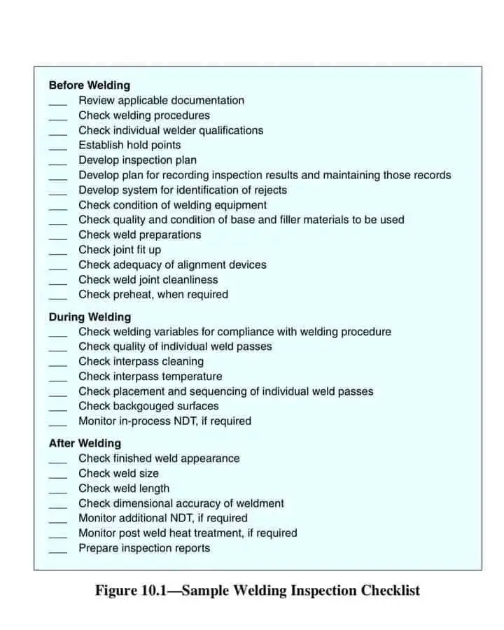
Welding inspection is conducted in three distinct phases: before welding (pre-weld), during welding (in-process), and after welding (post-weld). Each phase has its own set of checks, documentation requirements, and acceptance criteria. Codes such as ASME Section VIII Div. 1, ASME B31.3, AWS D1.1, and ISO 3834 all mandate inspection activities at defined stages, and the Inspection and Test Plan (ITP) is the document that translates those code requirements into a project-specific, auditable inspection programme.
This guide provides a comprehensive, technically detailed checklist for all three inspection phases — covering documentation, material verification, fit-up, in-process parameter monitoring, NDT selection, PWHT verification, and records management. It is written to match the rigour expected of a working CWI or welding engineer operating under ASME, AWS, or ISO inspection regimes.
Pre-weld inspection is where defect prevention happens. Every non-conformance caught before the first arc is struck eliminates the far greater cost — in time, material, and project schedule — of rework after welding. This phase is the most document-intensive and sets the conditions for all subsequent inspection activities.
1. Review All Applicable Documentation
Confirm the approved Welding Procedure Specification is posted at or near the work station. Check that it covers the specific base material P-Number combination, filler F-Number, joint type, welding position, and thickness range for the joint being welded. A WPS that covers P1 groove welds in position 1G does not cover the same joint in position 6G. Check the WPS revision number against the project’s document register — only the current approved revision is valid.
Confirm that the isometric or fabrication drawing at the work front is the latest approved revision. Superseded drawings must be physically removed from the work area and marked void. Welding to an outdated drawing is a common cause of dimensional non-conformance and weld map traceability failures.
The ITP must be in place and understood by all inspection parties before fabrication commences. All hold points (H) and witness points (W) must be marked on the weld map or traveller. Third-party inspection agencies and client representatives must have received formal notification of the ITP in advance of any hold point being reached.
2. Verify Welder Qualification
Every welder must hold a current, valid WPQ certificate covering the process, material, position, and thickness range of the joint they are about to weld. Under ASME Section IX QW-322, welder performance qualifications expire after six months if the welder has not been engaged in the welding process they are qualified for. Verify the most recent production weld date against the WPQ expiry. A welder with an expired WPQ must not weld until requalification is completed.
Each welder must have a unique stamp or identification mark, and all production welds must be marked with the welder’s ID on the weld map, traveller, or directly on the joint (where permitted). This traceability is essential for responding to NDT non-conformances — if RT reveals a rejectable defect, the weld map identifies the welder and the WPS used, enabling root cause investigation.
3. Establish Recordkeeping and Rejection Systems
A weld traveller accompanies each weld joint from fit-up through final NDT acceptance. It records the WPS number, welder ID, fit-up acceptance, preheat measurement, welding parameters, NDT results, and final disposition. Every inspection sign-off must be by name, certification, date, and time. Blank fields on a traveller are a non-conformance during audit.
Any component or joint that fails an inspection stage must be immediately identified with a rejection tag and physically segregated from accepted work. Yellow tags (hold) and red tags (reject) are the standard convention in most QA systems. Rejected items must not be moved to the next work stage until the non-conformance has been formally dispositioned — repair, rework, or use-as-is with engineering concurrence.
4. Inspect Welding Equipment and Consumables
Verify that the welding power source amperage and voltage meters are calibrated and within their calibration validity period. Check cables, earth clamps, gas hoses, and torch/gun condition for damage or wear. A poor earth connection causes arc instability that directly affects weld quality. Record the equipment serial number on the weld traveller — if a defect is later found in a production weld, the equipment used can be traced and tested.
Check the heat number on the base material against the material test report (MTR/CMTR). The MTR must confirm that chemical composition, mechanical properties, and heat treatment comply with the applicable material specification. For pressure equipment under ASME, all pressure-boundary material must carry ASME-required markings and be traceable to an MTR. Verify that the P-Number on the MTR matches the P-Number stated in the WPS.
Confirm that the filler metal classification (e.g., E7018-H4R, ER308L) matches the WPS requirement. Check the filler metal manufacturer’s certification for compliance with the applicable SFA specification. Low-hydrogen SMAW electrodes (E7016, E7018) must be stored in a heated oven at 120–150°C after opening — inspect the oven temperature log. Filler wires must be free from surface corrosion, and GTAW wires must be clean and dry. Contaminated or improperly stored consumables are a leading cause of hydrogen cracking and porosity. For more on consumable classification systems, see our dedicated guide.
5. Inspect Joint Preparation and Fit-Up
Inspect the bevel angle, root face, and root gap against the WPS and drawing requirements using a weld gauge or protractor. Common WPS requirements for single-V groove welds: included angle 60–70°, root face 1–1.5 mm, root gap 2–3 mm. Deviations from the qualified range are changes to a non-essential variable (generally) but may affect fusion quality if outside practical limits. Record actual measured dimensions on the traveller. See our guide on welding joint types and geometry for reference values by joint configuration.
Measure and record joint alignment (offset/hi-lo) across the joint interface. ASME B31.3 Process Piping limits hi-lo (axial misalignment) to 1.5 mm or 1/4 of the nominal wall thickness, whichever is less. AWS D1.1 permits a maximum root pass hi-lo of 3 mm before correction. Excessive hi-lo concentrates stress at the inside weld toe and is a fatigue crack initiation site in cyclic service. Confirm the root gap is within the WPS range and consistent around the circumference for pipe joints.
Inspect the joint faces and adjacent base metal surfaces (typically 25 mm back from the weld toe) for oil, grease, paint, mill scale, rust, moisture, and other contaminants. Any contamination within the weld zone is a source of porosity, hydrogen cracking, or inclusions. Clean using a dedicated stainless wire brush (for stainless and nickel alloys), appropriate degreasing solvent, or grinding — never use tools shared with carbon steel on stainless steel joints. For austenitic stainless, any iron contamination risks pitting corrosion in service.
Confirm that the preheat temperature required by the WPS has been achieved and is uniform across the joint before the root pass commences. Measure with a calibrated contact thermometer or Tempilstik at a point approximately 75 mm from the weld centreline for wall thicknesses above 50 mm, or 38 mm for thinner material (per AWS D1.1). Colour estimation of preheat temperature is not acceptable. For carbon and low-alloy steels, preheat prevents hydrogen-induced cracking (HICC) by keeping the HAZ above the martensite start temperature during cooling. Use our carbon equivalent calculator to determine minimum preheat requirements from base material chemistry.
In-process inspection monitors the welding operation in real time to ensure that the welder stays within the WPS parameter envelope and that each weld pass is acceptable before the next one is deposited. Defects caught during welding are far cheaper to repair than those found by post-weld NDT — grinding out a single bad pass costs minutes; excavating and rewelding a completed joint costs hours and may require re-qualification of the repair procedure.
1. Monitor Welding Parameters Against WPS
Confirm that the welding current, arc voltage, and travel speed measured during each pass fall within the ranges specified in the WPS. Use a calibrated clamp-on ammeter and voltmeter — do not rely on the machine’s built-in display, which may have been knocked out of calibration. Travel speed should be timed over a measured bead length (e.g., time in seconds to travel 100 mm). From these three parameters, calculate heat input per pass: H = (V × I × 60) / (TS × 1000) kJ/mm. For heat-sensitive materials such as P91 chrome-moly and duplex stainless steel, heat input is a controlled essential variable and must be recorded for every pass.
For GTAW and GMAW processes, verify the shielding gas cylinder label matches the WPS-specified composition (e.g., 100% Ar for TIG, Ar/CO₂ blend for MIG). Check the flow meter setting against the WPS range. Wind shields must be in place for outdoor or draughty work areas — excessive wind disperses the shielding envelope and causes porosity. For back-purge on stainless steel piping, monitor residual oxygen content at the purge outlet with a calibrated O₂ analyser; back purge must read below 0.10% O₂ before and throughout root welding.
2. Inspect Each Weld Pass
After completing each weld pass and before starting the next, the inspector (or welder acting as inspector) must examine the pass surface for: cracks (always an immediate stop-work condition), porosity, arc strikes outside the groove, slag entrapment along the fusion line, incomplete fill at the toes, and cold lap. Any rejectable condition must be removed by grinding or gouging and verified clean before the next pass is allowed. This inter-pass visual check is mandated by AWS D1.1 Clause 6.25 and ASME Section IX QW-194.
All slag, flux residue, and surface oxides must be removed between passes using a chipping hammer followed by a wire brush. Particular attention must be paid to the toes of the previous bead, where slag trapping is most common. For SAW and SMAW, slag removal is critical — any remaining slag becomes a planar inclusion in the next pass, which RT will detect as a linear indication. Check that only approved tools are being used — wire brushes for stainless must never be shared with carbon steel to prevent iron contamination and subsequent pitting corrosion.
Measure interpass temperature at the weld toe before every subsequent pass commences. The measurement point must be within 25–75 mm of the joint, depending on the applicable specification. Record actual readings on the weld traveller alongside the pass number. If the maximum interpass temperature specified in the WPS is exceeded, welding must stop and the joint allowed to cool. On P91 and P92 chrome-moly steels, excessive interpass temperature causes grain coarsening in the HAZ and promotes Type IV creep cracking sites. On duplex stainless steels, it drives sigma phase precipitation. Neither failure mode is detectable by standard production NDT — they are revealed only in service or by metallurgical sectioning during root cause investigation.
Confirm that the welder is following the pass sequence specified in the WPS or associated weld procedure detail. For multi-pass welds, the sequence affects residual stress distribution, HAZ tempering, and distortion. A balanced welding sequence on double-sided groove welds (alternating sides) minimises angular distortion. For piping welds in fixed positions, the recommended practice is to divide the weld into four clock-face quadrants and balance the fill sequence to minimise ovality and end-of-weld distortion.
Where the WPS specifies backgouging from the second side (common on double-sided groove welds and fillet repair welds), inspect the gouged surface before welding resumes. The backgouged groove must be: free from remaining weld metal not yet fused into the root (verified visually and by MT or PT if specified); smooth and free from sharp notches that would cause localised stress concentration; and ground clean of carbon contamination if carbon arc gouging was used (mandatory for stainless steel and chrome-moly alloys). For in-process NDT requirements (MT or UT on intermediate passes for thick-section welds), follow the specific requirements of the applicable code or project specification.
Post-weld inspection provides the final confirmation that the completed weld joint meets all applicable code and project requirements. It begins with visual examination — which is always the first and mandatory inspection method — and progresses through dimensional verification, NDT, and PWHT monitoring as required. No joint may be accepted or released for pressure testing, painting, or final assembly without full post-weld inspection sign-off.
1. Visual Inspection of the Finished Weld
Visual examination (VT) of the completed weld is mandatory under all construction codes and is the prerequisite for any other inspection method. VT must be performed in accordance with AWS QC1 or the applicable code by a qualified inspector with adequate lighting (minimum 500 lux at the weld surface per ISO 17637). Inspect the weld cap and both weld toes for: cracks, crater cracks, and HAZ cracking; undercut depth (measured with a weld undercut gauge — maximum 0.25 mm for cyclic service per AWS D1.1, 0.8 mm for static per D1.1 Table 9.1); overlap or cold lap at toes; surface porosity; excessive or insufficient reinforcement; and weld spatter within the inspection zone. Every visual observation must be recorded on the inspection form — not just rejectable conditions.
For fillet welds: measure throat thickness (minimum specified on drawing) and leg length at multiple locations around the joint. AWS D1.1 requires that leg length shortfall exceeding 2 mm in any 50 mm of weld length be repaired. For groove welds: measure reinforcement height (cap height above flush) — maximum 3 mm for most structural codes. Verify that the weld length on fillet welds matches the drawing specification. Use a calibrated weld gauge (Bridge Cam, Hi-Lo gauge, or equivalent) — engineer’s scale estimation is not acceptable for code inspection. Record all measurements with the gauge type and calibration reference number.
2. Dimensional and Geometric Verification
Measure the completed weldment against the dimensional tolerances on the fabrication drawing for: overall length; squareness and angularity; straightness (bow or sweep) of the assembly; flatness of flat surfaces; flange face perpendicularity and bolt-hole orientation on piping spools; and nozzle projection and orientation on pressure vessels. For piping spools, dimensional tolerances are typically governed by the construction standard (e.g., ASME B31.3 or the piping specification) and the client’s spool dimensional control procedure. Out-of-tolerance conditions may require cutting and re-welding rather than mechanical force correction, which can introduce residual stress.
3. Non-Destructive Testing
Conduct all NDT methods specified in the ITP, project specification, and construction code. Every NDT examination must be performed by a certified examiner (minimum Level II per SNT-TC-1A or ISO 9712), using a calibrated, written, and approved examination procedure. NDT results must be documented on a formal report that includes: examiner name, certification level, and expiry date; procedure number and revision; equipment identification and calibration status; examination coverage (percentage or area); and the accept/reject disposition with reference to the applicable acceptance standard. The NDT report must be signed by the Level II or III examiner and reviewed by the responsible inspector. For a comprehensive overview of all NDT methods used in welding, see our guide on non-destructive testing methods.
4. Post-Weld Heat Treatment Monitoring
If PWHT is required by the WPS or construction code, verify: the number and location of thermocouples meet the applicable code requirement (ASME Section VIII Div. 1 UCS-56 typically requires at least one thermocouple per 10 metres of heated length or part thereof, plus one at each end of the soak band); the actual soak temperature is within the code-specified range (e.g., 595–720°C for P1 carbon steel under ASME, depending on thickness); the hold time at temperature meets the code minimum; and the heating and cooling rates are within the specified limits (typically 55–220°C/hour maximum for carbon steel depending on thickness). The original chart recorder strip or data logger output is a permanent quality record — it cannot be rerun or reproduced if lost. Hardness testing after PWHT is required for sour service and certain alloy steel weldments to verify the PWHT achieved the target reduction in HAZ hardness.
5. Compile and Issue Final Inspection Reports
The completed weld documentation package for each joint or weld line must include: the completed weld traveller with all inspection sign-offs; the approved WPS referenced; welder ID and WPQ certificate reference; material traceability (MTR/CMTR references for base and filler materials); pre-weld inspection report; in-process parameter records; all NDT reports with examiner certifications; PWHT chart and thermocouple calibration records (where applicable); any NCR reports and their disposition records; and the dimensional inspection record. The inspector must sign the final acceptance statement on the traveller. Only after complete documentation sign-off may the joint proceed to pressure testing, painting, or final assembly. No documentation gaps are acceptable — every blank field on a weld traveller that was not completed at the time of inspection is a non-conformance.
NDT Method Selection — Defect Type vs. Technique
Selecting the correct NDT method requires understanding both the type of defect anticipated and the physical constraints of the weld joint. The following table summarises the applicability and limitations of the principal NDT methods used in welding inspection.
| NDT Method | Defect Type Detected | Applicability | Limitation | Code Reference |
|---|---|---|---|---|
| Visual Testing (VT) | Surface only | All materials; mandatory for every weld | Open to surface defects only; lighting and access critical | AWS QC1; ISO 17637; ASME V Art. 9 |
| Radiographic Testing (RT) | Volumetric | Butt welds; pipe and plate; all materials | Less sensitive to planar defects parallel to beam; radiation hazard; film archiving | ASME V Art. 2; AWS D1.1 Annex I; ISO 17636 |
| Ultrasonic Testing (UT / PAUT) | Volumetric + planar | All materials; thick sections; preferred for planar cracks | Operator skill-dependent; rough surfaces reduce coupling | ASME V Art. 4; AWS D1.1 Annex K; ISO 17640 |
| Magnetic Particle Testing (MT) | Surface + near-surface | Ferromagnetic materials (carbon steel, low-alloy) only | Not applicable to austenitic SS, aluminium, or non-magnetic alloys | ASME V Art. 7; AWS D1.1 Annex C; ISO 17638 |
| Liquid Penetrant Testing (PT) | Surface open only | All materials including non-magnetic (SS, aluminium, titanium) | Open-to-surface defects only; rough weld surfaces require dressing first | ASME V Art. 6; AWS D1.1 Annex D; ISO 3452 |
| Eddy Current Testing (ET) | Surface + near-surface | Conductive materials; tube inspection; surface crack detection | Not effective for deep subsurface defects; complex geometry limitation | ASME V Art. 8; ISO 15548 |
| Time of Flight Diffraction (TOFD) | Volumetric + planar | Pressure vessels; thick-section butt welds; high sensitivity | Dead zones near surface; complex analysis; operator qualification | ASME V Art. 4 App. N; ISO 10863 |
Visual Inspection Acceptance Criteria — Key Parameters
The following table consolidates key visual acceptance criteria from AWS D1.1 (structural steel) and ASME Section VIII Div. 1 (pressure vessels) for quick reference. Always confirm against the specific code edition and applicable project specification — these values represent the minimum code requirement and project specifications may be more restrictive.
| Discontinuity | AWS D1.1 (Static) | AWS D1.1 (Cyclic) | ASME Section VIII | Disposition |
|---|---|---|---|---|
| Cracks (any) | Reject | Reject | Reject | Remove by grinding; verify by MT/PT; reweld per approved repair WPS |
| Undercut depth | Max 1 mm; 0.25 mm at weld ends | Max 0.25 mm | Max 0.8 mm (UW-35) | Grind and blend; do not weld fill without WPS coverage |
| Groove weld reinforcement (cap height) | Max 3 mm | Max 3 mm | Max 3 mm (UW-35) | Grind flush if exceeded; ensure no undercut is introduced |
| Overlap (cold lap) | Reject | Reject | Reject | Remove by grinding; reweld affected area |
| Porosity (surface) | Max 6 mm cluster per 300 mm weld | Not permitted | Not permitted per UW-51 for RT-required welds | Individual pores > 2 mm: reject and repair |
| Arc strikes | Not permitted | Not permitted | Not permitted (UW-36) | Grind flush; MT/PT; document on NCR |
| Weld profile (fillet — convexity) | Max 0.07 leg length + 1.5 mm | Flush preferred | Per applicable code or drawing | Grind if excessive; check throat is maintained after grinding |
| Fillet weld throat deficiency | Max 2 mm, in ≤ 10% of weld length | Max 2 mm in any 150 mm | Per drawing minimum size | Deposit additional weld metal per WPS |
Why a Formal Welding Inspection Checklist Is Non-Negotiable
In regulated industries, the welding inspection checklist is not a discretionary quality improvement tool — it is a code-mandated requirement. ASME Section VIII Div. 1 Article UW-50 requires that all weld joints in pressure vessels be examined as specified by the applicable UW clauses. ISO 3834-2 Clause 12 requires documentation of all inspection activities. AWS D1.1 Clause 6 specifies the minimum inspection programme for structural steel welds. The ITP is the implementation document that maps these code requirements into the project’s specific inspection programme, with named hold points, responsible parties, and acceptance standards.
Beyond code compliance, a formal checklist delivers measurable operational benefits:
- Defect prevention: Pre-weld and in-process checks catch conditions before they become defects embedded in completed welds — dramatically reducing NDT failure rates and rework costs.
- Consistency: A checklist eliminates reliance on individual inspector memory. Every joint receives the same systematic examination regardless of shift, inspector, or project pressure.
- Traceability: Signed inspection records create an audit trail that demonstrates due diligence to clients, regulatory bodies, and insurance underwriters.
- Reduced rework: Industry data consistently shows that pre-weld fit-up inspection alone reduces NDT rejection rates by 30–50% on complex fabrication projects.
- Legal protection: In the event of an in-service failure, comprehensive inspection records are the primary evidence that the manufacturer exercised reasonable care and followed the applicable code.
Recommended Reference Books for Welding Inspectors
The following titles are the most widely used study and reference resources for practising CWIs, welding quality engineers, and inspection supervisors.
Disclosure: WeldFabWorld participates in the Amazon Associates programme (StoreID: neha0fe8-21). If you purchase through these links, we may earn a small commission at no extra cost to you. This helps support free technical content on this site.