Welding Symbols — Complete AWS A2.4 Guide for Beginners and Professionals
Welding symbols are the universal language of fabrication drawings. Defined by AWS A2.4 (Standard Symbols for Welding, Brazing, and Nondestructive Examination) in North America and ISO 2553 internationally, welding symbols convey in a compact graphic notation exactly what type of weld is required, where it goes, how large it must be, and what supplementary operations are needed — without a word of written description. Every engineer, drafter, welder, and welding inspector who works with fabrication drawings must be able to read welding symbols fluently.
A misread welding symbol can mean the wrong weld type, the wrong size, weld on the wrong side of the joint, or missed PWHT requirements. In pressure vessel and structural fabrication, such errors translate directly into failed inspection, costly repairs, and schedule overruns. This guide covers every element of the welding symbol system in the depth needed for real fabrication practice — from the basic arrow-side / other-side convention through to complete joint penetration groove weld notation, intermittent fillet weld designation, and process references in the tail.
You will also find original SVG diagrams for every major concept, a complete weld symbol library, worked reading examples step by step, and a comparison of the AWS A2.4 and ISO 2553 systems. For related drawing interpretation topics, see the guide to welding joint types and the article on welding positions and their designations.
Why Welding Symbols Matter
In fabrication practice, weld joints are designed by engineers, detailed by drafters or CAD operators, manufactured by welders, and inspected by quality inspectors — typically in different locations and often at different times. Welding symbols are the mechanism that transfers the design intent precisely through all of these handoffs without ambiguity.
The specific benefits of a correctly used welding symbol system are:
- Clarity and consistency — any qualified reader anywhere in the world (using the same standard) interprets the symbol identically, eliminating verbal misunderstandings
- Precision — a welding symbol specifies type, size, length, pitch, position, process, and finish in a single compact notation that would otherwise require a lengthy written note
- Cost reduction — incorrect welds (wrong size, wrong type, wrong side) are caught at the drawing stage rather than after fabrication, avoiding expensive repairs
- Document control — welding symbols on drawings create a permanent, auditable record of the design intent, which is essential for code compliance (ASME, AWS D1.1, API 1104)
Weld Symbol vs Welding Symbol — Key Distinction
AWS A2.4 makes a precise and important distinction between two closely related terms that are frequently confused:
Weld Symbol
The graphical element that identifies the type of weld required. Examples: a triangle = fillet weld; a V shape = V-groove weld; a square = square groove. The weld symbol alone conveys only the type — it says nothing about size, location, or supplementary requirements.
Welding Symbol
The complete assembly that appears on the drawing. It includes the weld symbol plus the reference line, arrow, dimensions, supplementary symbols, tail, and any other modifiers. The welding symbol as a whole conveys the complete fabrication instruction for that joint.
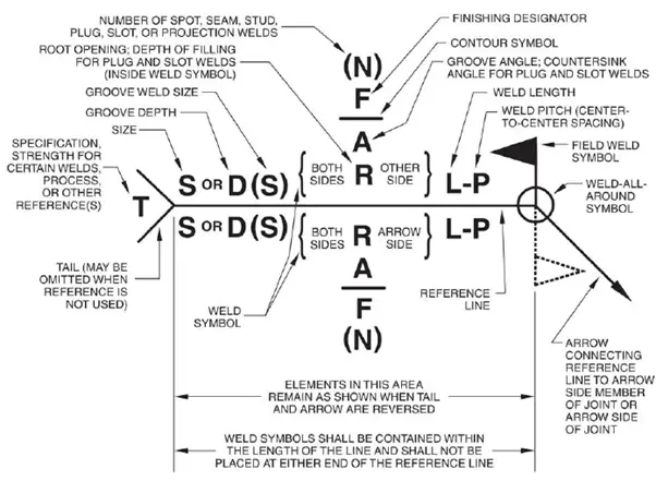
Complete Components of a Welding Symbol
AWS A2.4 defines up to eight distinct elements that may appear in a complete welding symbol. Not every welding symbol uses all eight — many simple symbols use only three or four. The table below summarises every element, its location relative to the reference line, and when it is required.
| # | Element | Location on Symbol | Purpose | Required? |
|---|---|---|---|---|
| 1 | Reference line | Horizontal baseline | Anchors all other elements; direction of reading is left to right | Always |
| 2 | Arrow | One end of reference line | Points to the joint, location, or area to be welded | Always |
| 3 | Weld symbol | On the reference line (above or below) | Indicates the type of weld (fillet, groove, plug, spot, etc.) | Always |
| 4 | Dimensions | Left and right of weld symbol | Specifies size, length, pitch, depth, angle, root opening | When required |
| 5 | Supplementary symbols | At arrow/reference junction or on symbol | All-around circle, field weld flag, backing bar, melt-through, spacer | When required |
| 6 | Contour symbol | Above or below the weld symbol | Specifies weld face profile: flush, convex, or concave | When required |
| 7 | Finish symbol | Adjacent to contour symbol | Specifies finishing method: G (grind), M (machine), C (chip), R (roll), U (unspecified) | When required |
| 8 | Tail | End of reference line opposite arrow | References WPS, process (GTAW, SMAW, etc.), filler metal, or special notes | Optional |
The Reference Line
The horizontal reference line is the foundation of every welding symbol. All other elements are positioned relative to it. The reference line always appears as a straight, horizontal line on the drawing, regardless of the orientation of the joint itself. Key rules for the reference line:
- The reference line is always drawn horizontally — never at an angle — even if the joint is inclined
- The arrow connects to one end (either end — the standard permits both)
- The tail, when used, occupies the opposite end from the arrow
- Below the reference line = arrow side of the joint
- Above the reference line = other side (the side opposite the arrow)
- When weld symbols appear both above and below, welding is required on both sides
The Arrow and Arrow-Side Convention
The arrow connects to the reference line and points to the joint to be welded. In most cases the arrow is a simple straight line with an arrowhead at the joint end. AWS A2.4 makes one important special case: the break arrow.
Break Arrow (Arrow with Bend)
For certain groove welds — particularly bevel and J-groove welds — one member of the joint must be prepared (beveled or formed) while the other remains square-cut. In these cases, the standard requires a break (a bend or kink) in the arrow line. The break in the arrow is always directed toward the member that must be prepared. This removes any ambiguity about which piece the groove must be cut into.
Arrow-Side and Other-Side Convention Summary
| Situation | Weld Symbol Position | Meaning |
|---|---|---|
| Weld on the face the arrow touches | Below reference line | Arrow-side weld |
| Weld on the opposite face | Above reference line | Other-side weld |
| Weld on both faces | Both above and below | Both-sides weld |
| No side preference | Centred on reference line | Used for spot, seam, plug, and resistance welds |
Basic Weld Symbol Library
The weld symbol identifies the type of weld required. AWS A2.4 defines symbols for arc and gas welds, resistance welds, and brazing. The most commonly encountered symbols in structural and pressure vessel fabrication are shown below.

Arc and Gas Weld Symbols — Reference Table
| Weld Type | Symbol Description | Common Application | Groove? |
|---|---|---|---|
| Fillet | Right triangle — vertical leg on left | T-joints, lap joints, corner joints | No |
| Square groove | Two vertical parallel lines | Thin plate butt joints; full penetration on sheet metal | Yes |
| V-groove | Inverted V (chevron) | Butt joints in plate, pipe, structural; most common groove type | Yes |
| Bevel groove | One vertical line + one angled line (half V) | T-joints requiring full penetration; one-sided access only | Yes |
| U-groove | U shape on reference line | Thick plate where V-groove would require excessive fill; reduces distortion | Yes |
| J-groove | J shape — one vertical + one curved | T-joints requiring full penetration with reduced weld volume | Yes |
| Flare-V groove | Two curved flanges forming a V | Joining two round or formed sections | Yes |
| Flare-bevel groove | One vertical + one curved flange | Joining a flat plate to a round or formed section | Yes |
| Plug | Circle on reference line | Filling a hole in the top member with weld metal; resists shear | No |
| Slot | Rectangle on reference line | Elongated plug weld; used when single plug is insufficient | No |
| Spot (arc) | Circle centred on reference line | Sheet metal spot welds; no hole required (unlike plug) | No |
| Seam (arc) | Circle with two horizontal bars through it | Continuous or intermittent seam welds in thin sheet | No |
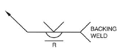
| Back / Backing | Semicircle on reference line (back of groove) | Back weld deposited after initial groove; backing weld on the other side first | With groove |
| Surfacing | Three horizontal lines stacked | Build-up overlays, hard-facing, cladding applications | No |
Supplementary Welding Symbols
Supplementary symbols add specific requirements that cannot be conveyed by the basic weld symbol alone. AWS A2.4 defines five key supplementary symbols in common use:
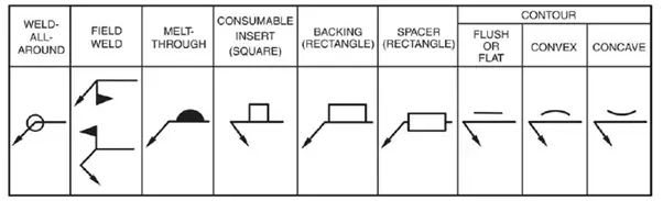
| Supplementary Symbol | Appearance | Meaning | Placement |
|---|---|---|---|
| All-around | Small open circle at arrow-reference junction | Weld must continue completely around the perimeter of the joint | At junction of arrow and reference line |
| Field weld | Solid filled flag (pennant) at arrow-reference junction | Weld is to be made in the field (not in the fabrication shop) | At junction of arrow and reference line |
| Melt-through | Filled (solid) semicircle on reference line | Complete joint penetration from one side with visible root reinforcement on the other | Opposite side from groove weld symbol |
| Backing bar | Rectangle on reference line (other side from groove) | A separate backing material is used to support the root pass; R in rectangle = remove after welding | Other side of reference line from groove symbol |
| Spacer | Rectangle centred on reference line | A separate insert/spacer is to be fused into the joint root | Centred on reference line |
| Flush contour | Flat horizontal line on weld symbol | The weld face must be flush (even) with the surrounding base metal surface | Above or below the weld symbol (same side) |
| Convex contour | Convex arc on weld symbol | The weld face must have a convex (crowned) profile | Above or below the weld symbol (same side) |
| Concave contour | Concave arc on weld symbol | The weld face must have a concave (hollow) profile | Above or below the weld symbol (same side) |
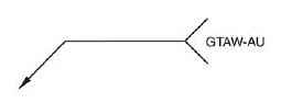
The Tail — Process and Specification References
The tail is a forked extension at the end of the reference line opposite the arrow. When no additional information is required, the tail is omitted entirely. When present, it carries information in a standardised shorthand notation. AWS A2.4 permits the following information in the tail:
- Welding process designation — AWS letter abbreviations such as GTAW (TIG), SMAW, GMAW, FCAW, SAW, PAW, EBW
- WPS reference — the specific welding procedure specification number, e.g., “WPS-014”
- Filler metal classification — e.g., “ER308L” or “E7018”
- Special inspection requirements — e.g., “RT” or “PT” to indicate that specific NDT is required at that joint
- Peening, backgouging, or other special operations
- Strength requirements — for certain codes that permit specifying minimum weld strength in the symbol
Weld Dimensions and Their Placement
Weld dimensions are always placed on the same side of the reference line as the weld symbol. Their precise location (left or right of the symbol) is standardised and must be observed correctly:
Fillet Weld Dimensions
For intermittent fillet welds (chain or staggered), the designation “6-50-150” means: 6 mm leg size, 50 mm weld length, 150 mm pitch (centre-to-centre spacing). Chain intermittent welds use identical symbols above and below the reference line. Staggered intermittent welds use symbols that are offset (staggered) above and below.
Groove Weld Dimensions
| Dimension | Abbreviation | Position on Symbol | Notes |
|---|---|---|---|
| Groove depth | S | Left of symbol, in parentheses: (S) | Depth of groove cut into base metal; for PJP welds |
| Effective throat / weld size | E | Left of symbol, after S: (S)(E) | The load-bearing dimension; may differ from groove depth |
| Root opening | R | Inside the groove symbol | Gap between joint faces at the root |
| Groove angle | A | Inside the groove symbol | Total included angle of the groove in degrees |
| Leg size (fillet) | z | Left of fillet symbol | For equal-leg fillets one value suffices; unequal legs use two values |
| Weld length | l | Right of weld symbol | For intermittent welds; omit if continuous weld |
| Pitch | p | Right of length, after hyphen: l-p | Centre-to-centre spacing for intermittent welds |
Weld Contour and Finish Symbols
The contour symbol specifies the required profile of the weld face after welding. The finish symbol specifies the method by which that contour is achieved.
| Contour Type | Symbol | Application |
|---|---|---|
| Flush | Straight horizontal line above/below weld symbol | Required when weld face must be level with the base metal — common in groove welds for fatigue-sensitive joints and pipe runs where internal smoothness matters |
| Convex | Convex arc above/below weld symbol | Specified when a slight crown is acceptable or desired; the default as-welded fillet profile is naturally convex |
| Concave | Concave arc above/below weld symbol | Common on fillet welds in fatigue applications; a concave fillet reduces toe stress concentration; typically produced by finishing |
Finish symbols appear adjacent to the contour symbol and specify the method used to achieve the required profile:
| Finish Symbol Letter | Method | Use |
|---|---|---|
| G | Grind | Most common; angle grinder or disc grinder to achieve flush or concave profile |
| M | Machine | Lathe, milling, or similar precision machining; used in high-accuracy or high-pressure applications |
| C | Chip | Chipping hammer for rough dressing; rarely specified as a final finish |
| R | Roll | Roll-forming or planishing; used in sheet metal work |
| U | Unspecified | Contour required but finishing method is left to the fabricator’s discretion |
Reading Welding Symbols — Worked Examples
The following worked examples take you through the step-by-step process of reading complete welding symbols of increasing complexity. This is the skill that separates a drawing interpreter from someone who has only memorised symbol shapes.
Example 1 — Simple Arrow-Side Fillet Weld
Example 2 — Double Fillet Weld with Length and Pitch
Example 3 — Single-V Groove with Root Opening and CJP
Example 4 — Partial Penetration Groove with GTAW in Tail
AWS A2.4 vs ISO 2553 — Key Differences
Engineers working internationally encounter both AWS A2.4 (North American) and ISO 2553 (international) systems on the same project. The two standards use the same concept — a reference line — but have important differences in convention that must be understood to avoid misreading.
| Feature | AWS A2.4 | ISO 2553 |
|---|---|---|
| Arrow-side identification | Weld symbol placed below the reference line | Weld symbol placed on the reference line (no above/below rule for arrow-side) |
| Other-side identification | Weld symbol placed above the reference line | A dashed identification line is added below the reference line; symbol placed on the dashed line for other side |
| Symbol orientation | V-groove symbol points upward (chevron up) | V-groove symbol points downward (chevron toward joint surface) |
| Tail usage | Used for process, WPS, filler metal, NDT | Same concept; ISO uses a forked tail (flag) but notation is similar |
| Weld size notation | Leg size (fillet) to left of symbol | ISO uses “z” prefix before leg size, e.g., z6 |
| All-around symbol | Circle at arrow/reference junction | Same symbol |
| Field weld symbol | Filled flag at junction | ISO does not have an equivalent standard field weld symbol; a note is used |
| Primary usage | USA, Canada, and AWS-governed projects globally | Europe, Asia, Australia, and most international projects |
Recommended Reference Books on Welding Symbols and Drawing Interpretation
Disclosure: WeldFabWorld participates in the Amazon Associates programme (StoreID: neha0fe8-21). If you purchase through these links, we may earn a small commission at no extra cost to you. This helps support free technical content on this site.