Cold Welding — Complete Guide: Physics, Process, Metals, Applications and Space Engineering
Cold welding is one of the most conceptually fascinating processes in all of joining technology. It produces a permanent, full-strength metallurgical bond between two metal surfaces using no heat whatsoever — no arc, no flame, no electrical resistance, no filler metal. Instead, it exploits a fundamental principle of physics: that atoms of the same element have no reason to remain separate if there is nothing between them. Strip away the oxide layers that form on every metal surface exposed to air, press the two clean faces together under sufficient force, and the atoms on one surface cannot distinguish themselves from the atoms on the other. The joint forms spontaneously, at room temperature, as if the two pieces had always been one.
The American Welding Society (AWS) defines cold welding formally as “a solid-state welding process in which joining takes place without fusion or heating at the interface of the two parts to be welded.” In practice it is used to join electrical conductor wires, extend wire stock, seal heat-sensitive containers, join dissimilar metals that cannot be fusion welded, and — in its most unexpected manifestation — to accidentally seize spacecraft mechanisms in the vacuum of space. Most recently, the ASTROBEAT experiment launched to the International Space Station on 5 November 2024 is investigating cold welding as a deliberate repair method for spacecraft hull damage from space debris impacts, representing a complete reversal of the process’s traditional status as a hazard to be avoided.
What Is Cold Welding — AWS Definition and Classification
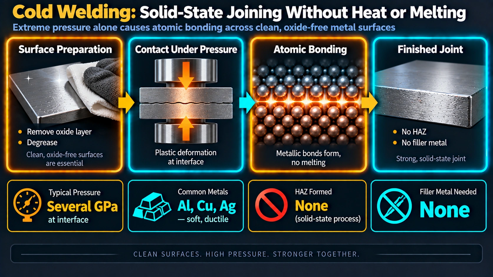
Cold welding — also known as cold pressure welding or contact welding — is classified by AWS as a solid-state welding (SSW) process. Solid-state welding encompasses all processes in which joining occurs without a molten phase at the joint interface. Cold welding shares this category with friction welding, explosion welding, ultrasonic welding, and diffusion bonding — but it is unique within this group because it requires neither elevated temperature nor relative motion between the workpieces. Pressure alone is sufficient when the surfaces are prepared correctly.
The process should be carefully distinguished from two similarly-named but fundamentally different processes: Cold Metal Transfer (CMT), which is a fusion arc welding variant of GMAW that uses an electric arc and filler wire, and “TIG Cold” welding, which refers to low-heat-input pulsed TIG settings on certain machines. Neither of these involves true solid-state bonding. Cold welding, by contrast, leaves no weld pool solidification structure, no fusion zone, no arc crater, and no HAZ — because none of these things are physically possible at ambient temperature.
The Physics of Cold Welding — Why Atoms Bond Without Heat
To understand cold welding, you need to understand what prevents two pieces of the same metal from bonding when you simply press them together in everyday life — and why that barrier disappears under the right conditions.
The Oxide Barrier Problem
Every metal surface exposed to air is covered by a thin layer of oxide formed by the reaction between the metal and atmospheric oxygen. For aluminium, this layer is Al2O3 (aluminium oxide) with a melting point of 2,072 °C — far above the metal itself (melting point 660 °C). For copper it is Cu2O and CuO; for iron it is Fe2O3. These oxide layers are electrically insulating, chemically stable, and mechanically different from the underlying metal. Crucially, they prevent the metal atoms beneath them from reaching the atomic proximity needed for metallic bonding.
“The reason for this unexpected behavior is that when the atoms in contact are all of the same kind, there is no way for the atoms to ‘know’ that they are in different pieces of copper. When there are other atoms, in the oxides and greases and more complicated thin surface layers of contaminants in between, the atoms ‘know’ when they are not on the same part.”
— Richard Feynman, The Feynman Lectures on Physics, Vol. 1, Chapter 12-5 “Friction”
Feynman’s insight captures the essence of cold welding precisely. Metallic bonding is the sharing of delocalised electrons in a crystal lattice — a “sea” of electrons holding positively charged metal ions in a regular pattern. When two clean surfaces of the same metal touch, the electron sea extends seamlessly across the interface. The bond forms not because the atoms were attracted to each other from a distance, but because there was nothing to tell them they were ever separate.
The Plastic Deformation Mechanism
In practice, achieving “perfectly clean surfaces in perfect contact” requires more than just removing visible contamination. Even after wire brushing, residual oxide particles, adsorbed moisture, and sub-monolayer impurities remain. The function of the applied pressure in cold welding is threefold: it forces the surfaces into intimate contact; it causes plastic deformation at the interface that extends and fractures the remaining oxide film, exposing virgin metal beneath; and it brings the newly exposed metal atoms to within the range of interatomic attractive forces (approximately 0.2–0.4 nm for metallic bonds).
The bond in a cold pressure weld is achieved by what researchers describe as “intimate mashing” of clean metal surfaces — the layers immediately adjacent to the interface are stretched, sheared, and kneaded together. Oxides fracture in a brittle manner and are pushed laterally to the edges of the contact zone. The virgin metal beneath flows together and forms atomic linkages. There is negligible interdiffusion: the bond forms essentially instantaneously by mechanical contact and electron sharing, not by atomic diffusion across the interface (which would require elevated temperature and time).
Threshold Deformation — The Critical Parameter
For each metal and joint geometry, there is a minimum amount of plastic deformation at the interface — called the threshold deformation — below which no bond forms regardless of how clean the surfaces are. Above this threshold, bond strength increases with deformation until it reaches the parent metal strength. Below it, the surfaces separate with no welding having occurred.
| Metal | Approx. Threshold Deformation | Notes |
|---|---|---|
| Aluminium (pure) | 40–60% reduction | Oxide film fractures readily; relatively low threshold |
| Copper | ~80% reduction (lap) / 50% (butt) | Higher threshold than Al; work-hardens more |
| Lead | ~10% reduction | Very soft, very low threshold — easiest to cold weld |
| Gold | Very low (<10%) | Noble metal — no oxide layer in air, almost no threshold |
| Silver | Low (<20%) | Minimal oxide formation; low threshold |
| Zinc | Moderate (~40%) | Brittle oxide breaks cleanly at moderate deformation |
| Nickel | High (~80%) | Stable oxide requires significant deformation to fracture |
Prerequisites and Surface Preparation for Cold Welding
Surface preparation is not merely an important step in cold welding — it is the step that determines whether any bonding will occur at all. Unlike fusion welding, where the molten pool partially expels contaminants and atmospheric protection from the shielding gas covers oxidation, cold welding has no self-cleaning mechanism. Every contaminant present on the surface at the moment of contact is mechanically trapped at the interface and weakens the bond proportionally to its area coverage.
- Degrease first — always before brushing. Remove all oils, greases, cutting fluids, and finger oils with acetone, methyl ethyl ketone (MEK), or isopropyl alcohol. This step is critical for soft metals like aluminium, copper, and gold: a wire brush will embed surface oils into the metal if they are not removed first, making them impossible to eliminate in later steps.
- Remove the oxide layer by wire brushing or mechanical shearing. After degreasing, use a stainless steel wire brush dedicated exclusively to that metal — never a brush previously used on steel or a different metal. Brush strokes should be in one direction. Soft brushes may burnish without removing oxides; coarse brushes may leave surface irregularities. For butt joints on wire and rod, a clean shear cut immediately before welding is the preferred method because the fresh-cut cross-section is virgin metal with minimal oxide.
- Minimise the time between preparation and welding. After brushing, oxides begin re-forming immediately upon atmospheric exposure. For aluminium, the maximum allowable time between preparation and welding is approximately 30 minutes. For other metals, welding should be completed as soon as possible. Never store prepared surfaces loose — re-clean if delayed.
- Never touch prepared surfaces with bare hands. Skin oils are invisible but contain fatty acids that adsorb onto fresh metal surfaces within seconds. Even touching the area adjacent to the weld zone with bare skin can contaminate it through capillary spread during deformation.
- Ensure joint geometry is correct. Flat butt joint surfaces (for wire and rod) or flat lap surfaces (for sheet) give the most consistent results. Any convexity or concavity in the contact face reduces the effective bonding area. For wire butt joints, the wire ends should be square-cut perpendicular to the axis — any angle reduces the contact area at the critical initial moment of pressure application.
- Account for lap joint thickness reduction. When cold-welding sheet metal in a lap configuration, plastic deformation under pressure will reduce the thickness at the joint by 40–60%. Design the joint with this in mind — the final part dimension, not the pre-weld dimension, must meet the design specification.
What Metals Can Be Cold Welded — Complete Material Guide
The suitability of a metal for cold welding is governed by two metallurgical criteria: crystal lattice structure and work-hardening behaviour. Metals with a face-centred cubic (FCC) crystal structure have twelve slip systems available for plastic deformation — meaning they can deform in many directions before work-hardening prevents further deformation. This makes FCC metals ductile enough to sustain the plastic deformation needed to break up oxide films and achieve atom-scale surface contact. Body-centred cubic (BCC) metals like iron and carbon steel have fewer slip systems and work-harden more aggressively, making cold welding impossible before the material fractures.
How Cold Welding Works — The Industrial Process
Cold Welding Wire and Rod — Butt Joint Method
The most common industrial application of cold welding is joining wire, rod, and strip stock using a butt joint configuration. The cold welding machine applies force through a set of dies that grip the workpieces near their ends and simultaneously push them together. The key principle is the multi-upset method: pressure is applied not once but a minimum of four successive times (upset cycles). Each upset drives out a small quantity of impurities from the interface toward the periphery. The combined effect of multiple upsets is a progressively cleaner and more intimate metal contact at the joint core, eventually achieving a full-strength bond.
The flash — the extruded metal expelled laterally from the joint during the upset cycles — is a visible confirmation that the process has occurred. It is chipped or machined off after welding to restore the original cross-sectional dimensions. The finished butt joint shows no visible interface when examined metallographically: the grain structure crosses the original joint plane as if the metal were always continuous.
| Machine Type | Wire/Rod Range | Actuation | Application |
|---|---|---|---|
| Handheld / portable | 0.5–6 mm diameter | Manual lever or ratchet | Field wire joining, small rod stock |
| Bench-top pneumatic | 2–20 mm diameter | Pneumatic cylinder | Workshop wire extension, electrical conductor joining |
| Industrial hydraulic | 10–80 mm diameter | Hydraulic / electro-hydraulic | Heavy conductor, rod and tube production |
| In-line production | Wire drawing lines | Automated, integrated into drawing line | Continuous wire production — joining coil ends without stopping |
Cold Welding Sheet — Lap Joint Method
Lap joints in sheet metal are produced by placing two prepared sheet metal overlaps in a flat press and applying sufficient force to achieve the threshold deformation. The key challenge is accounting for thickness reduction: a lap joint will reduce in thickness by 40–60% under the required pressure. This thinned zone must be factored into the structural design of the assembly. It is good practice to make test welds on representative material to determine the actual thickness reduction before committing to a production design.
Cold Weld Joint Types and Design Rules
Cold welding is most effective with joint geometries that provide large, uniform contact area and allow plastic deformation to expel impurities to the periphery. Only two joint types are used in practice.
| Joint Type | Applications | Design Rules | Thickness Change |
|---|---|---|---|
| Butt Joint | Wire joining, rod stock, tubing, electrical conductors | Square-cut ends perpendicular to wire axis; clamp distance from joint face should not exceed 1.5× diameter to prevent sideways buckling of soft metals | Axial shortening (flash extruded) — typically 10–25% of wire diameter per upset |
| Lap Joint | Sheet metal, strip, thin foil bonding | Design for 40–60% thickness reduction at joint — account in structural calculation. Test coupons required to determine actual reduction for specific metal and machine | 40–60% reduction at lap zone — this is unavoidable and must be designed-in, not treated as a defect |
Is Cold Welding Strong? — Joint Strength Analysis
A correctly executed cold weld achieves joint strength equal to the parent metal. Unlike fusion welding — where the HAZ is always weaker than the base metal due to grain coarsening and microstructural changes — a cold weld has no HAZ. The microstructure in the vicinity of the cold-welded interface is identical to the bulk material because no heat was applied. The grain structure is simply continuous across what was once the interface.
However, cold welding strength is fundamentally dependent on preparation quality in a way that fusion welding is not. Fusion welding’s liquid phase provides a partial self-cleaning mechanism; cold welding has none. The relationship between preparation quality and joint strength is essentially linear: any surface contamination that remains at the interface reduces bond strength proportionally to the area it occupies. A surface that is 10% contaminated will produce a joint that is approximately 10% weaker. Full-strength joints require full-coverage bonding of virgin metal atoms.
| Condition | Typical Joint Strength (% of Parent) | Root Cause |
|---|---|---|
| Optimal (correct prep + threshold deformation exceeded) | 95–100% | Full atom-scale contact, no contamination |
| Adequate (some minor residual oxide) | 70–90% | Small unbonded islands at interface |
| Poor (insufficient deformation or partial cleaning) | 30–60% | Large unbonded zones, weak adhesion only at high points |
| Failed preparation (oil or heavy oxide present) | <20% | No true metallic bond — only mechanical interlocking |
One important characteristic of cold welded joints is that the strength cannot exceed the parent metal strength — unlike fusion welds, which can in theory be stronger than the base metal through microstructural control of the solidified weld pool. In cold welding, the joint is literally the same material as the base, so it cannot be stronger. This is not a limitation in practice, since achieving 100% joint efficiency with 100% parent metal properties is the theoretical maximum for any joining process.
Cold Welding in Space — Engineering Hazard and Emerging Opportunity
Cold welding in space is the process’s most dramatic and consequential manifestation. In the vacuum of orbit, the thin oxide layers that form on every metal surface on Earth do not re-form after removal because there is no oxygen. Any time two clean metal surfaces are brought into contact in vacuum — even through the vibration of launch — they can cold weld permanently and instantaneously. This has caused real spacecraft failures and is the subject of active research at the European Space Agency and NASA.
The Galileo High-Gain Antenna Failure — Cold Welding in Action
The NASA Galileo spacecraft, launched in October 1989 toward Jupiter, carried a high-gain dish antenna designed to unfold from a compact furled configuration after launch. In April 1991, when controllers attempted to deploy the antenna, only 3 of the 18 ribs fully opened. The antenna remained 80% furled and was never successfully deployed — severely limiting the science data return from the Jupiter mission.
Investigation concluded that three ribs had cold-welded to their hold-down pins while in the furled position. The cause: vibrations during transport and launch on Earth had caused fretting (small oscillatory motion) at the aluminium rib-to-pin contact points. This fretting wore away the protective anodic coating on the aluminium, exposing bare metal. Once the bare metal surfaces were in contact without any protective coating, they cold-welded in the mild vacuum conditions encountered during transport and in the transition to deep space vacuum. The mission lost an estimated 99% of its planned science data return as a result.
The European Space Agency (ESA) published a peer-reviewed paper in 2009 specifically addressing cold welding as a design consideration for spacecraft, and in 2024 published updated testing procedures for spacecraft mechanisms at the 47th Aerospace Mechanisms Symposium.
ASTROBEAT — Cold Welding as a Spacecraft Repair Method (ISS, 2024)
In a remarkable reversal of its traditional status as a hazard, cold welding is now being deliberately investigated as a spacecraft repair technology. The ASTROBEAT (Advanced Space Technology Research On-Orbit for Bond Engineering And Testing) experiment was launched to the International Space Station on 5 November 2024 aboard SpaceX CRS-31, sponsored by the ISS National Laboratory and led by Leonardo Barilaro of the Malta College of Arts, Sciences, and Technology (MCAST).
The experiment is housed in a 1U CubeSat Nanolab installed on an ISS rack. It tests cold welding of CuSn4 (tin bronze) and Al-2024T metal pairs under controlled forces, simulating the application of repair patches to hull perforations caused by hypervelocity impacts from micrometeorites or orbital debris. The space environment provides a crucial advantage: without atmospheric oxygen, metal surfaces do not re-oxidise after preparation, meaning cold welding bonds can form at reduced contact forces compared with Earth-based applications.
“Cold welding has long been considered an adverse phenomenon in space,” said Barilaro, “but with ASTROBEAT, we’re transforming a problem into a viable repair mechanism.” If successful, the technology could allow astronauts to seal hull breaches in pressurised modules from the inside — using nothing more than a prepared metal patch and mechanical pressure — without the heat, electrical equipment, or specialist skills that conventional welding would require in the hostile environment of orbit.
Engineering Rules to Prevent Unintended Cold Welding in Space Mechanisms
ESA’s cold welding database (maintained by Aerospace and Advanced Composites GmbH, Austria) and the test standard STM-279 provide guidance for spacecraft designers. Key design rules include:
- Material dissimilarity: Use different alloys at metal-to-metal contact points — different metals have different oxide compositions and lower tendency to cold weld to each other than the same metal to itself
- Coatings and surface treatments: Anodising, gold plating, PTFE coatings, or molybdenum disulphide (MoS2) dry film lubricants at contact interfaces prevent bare metal-to-metal contact
- Lubrication: Space-grade lubricants (ionic liquids, perfluoropolyether oils) at mechanism contact points prevent direct metal contact
- Geometric separation: Ball-to-flat and convex-to-convex contact geometries concentrate contact stress over a smaller area, reducing the tendency to form welds compared with flat-to-flat contact
- Vibration dampening: Reducing fretting amplitude limits the wear that removes protective surface layers during launch vibration
Cold Welding in Electronics — Wire Bonding and Semiconductor Packaging
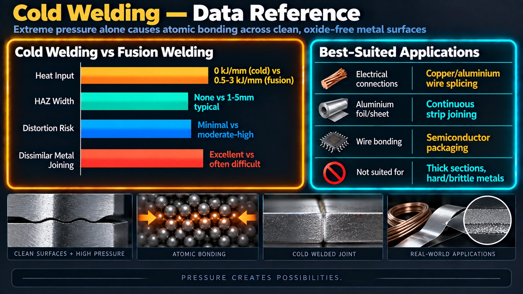
The most economically significant application of cold welding principles today is semiconductor wire bonding — the process of connecting the microscopic bonding pads on integrated circuit chips to the lead frames or substrates of the package. Wire bonding accounts for the vast majority of all chip-level interconnections in modern electronics, and the global semiconductor gold bonding wire market was valued at USD 1.2 billion in 2024, projected to grow at 9.1% CAGR to USD 2.5 billion by 2033.
Thermocompression Bonding (Cold Welding at Microscale)
Thermocompression (TC) bonding uses a combination of heat and pressure to deform a gold wire against a heated gold bonding pad surface, forming a metallurgical solid-state weld. While it does use heat (substrate temperature 150–400 °C), the bonding mechanism is fundamentally the same as cold pressure welding: pressure-driven plastic deformation brings clean metal surfaces to atom-scale contact, and electron sharing forms the metallic bond. It is cold welding assisted by heat to reduce the required pressure.
Thermosonic Bonding
Thermosonic bonding combines heat, ultrasonic energy, and pressure. The ultrasonic frequency scrubs the surface clean by oscillating the wire against the bonding pad at typically 60–120 kHz, breaking up any residual oxide and generating localised friction heat. The result is a more reliable bond at lower applied forces than thermocompression alone. Thermosonic bonding is the current standard for gold ball bonding in high-speed semiconductor assembly.
Nanoscale Cold Welding — Gold Nanowires
In 2010, researchers discovered that single-crystalline gold nanowires with diameters below 10 nm can be cold-welded together within seconds by mechanical contact alone, under remarkably low applied pressures — orders of magnitude lower than required for macroscopic cold welding. High-resolution transmission electron microscopy revealed that the welds are nearly perfect in crystal orientation, strength, and electrical conductivity. This phenomenon is explained by the nanoscale dimensions, oriented-attachment mechanisms, and mechanically-assisted fast surface diffusion — processes that are negligible at macro scale but dominant at nanoscale. It has been demonstrated for gold-gold, gold-silver, and silver-silver nanowire pairs, suggesting a potentially general phenomenon at atomic scale.
Cold Welding vs Hot Welding vs Cold Metal Transfer — Complete Comparison
Advantages and Limitations of Cold Welding
Advantages
- No heat — eliminates HAZ, grain coarsening, thermal distortion, and residual stress entirely
- No HAZ — weld zone microstructure identical to parent metal
- No arc, no flame — can be used in explosive, flammable, or oxygen-sensitive environments
- No filler metal — weld chemistry exactly matches base metal
- Joins dissimilar metals (Cu-Al, Au-Ag) without brittle intermetallic compounds
- Can weld aluminium grades (2xxx, 7xxx) that cannot be fusion welded
- No porosity, no solidification cracks — defect modes of fusion welding are impossible
- Full joint strength equals parent metal when correctly executed
- No operator skill in arc control — repeatable machine process
- Suitable for explosive or heat-sensitive containment applications
- Electrical conductivity fully preserved — ideal for electrical conductor joining
- Underground or underwater applications safe — no electrical hazard
Limitations
- Carbon steel and any carbon-containing metal: impossible to cold weld
- Only ductile, non-work-hardened FCC metals are suitable
- Meticulous surface preparation is mandatory — no self-cleaning mechanism
- Limited time window between preparation and welding (~30 min for Al)
- Irregular shapes are very difficult — flat surfaces and circular sections only
- Lap joints unavoidably reduce thickness by 40–60% — must be designed-in
- Industrial application limited mainly to wire, rod, strip, and thin sheet
- Very difficult to achieve in dusty or contamination-rich environments
- Equipment cost for pneumatic/hydraulic machines is higher than basic arc welders
- Cannot weld thick sections — applied force requirements become impractical
- In space: represents an uncontrolled hazard to mechanisms and requires specific design precautions
Cold Welding Applications — Industry by Industry
| Industry | Application | Why Cold Welding? | Metals Used |
|---|---|---|---|
| Electrical Power Distribution | Copper-to-aluminium overhead conductor butt joints; busbar connections | No intermetallics; full electrical conductivity; no fumes near insulation | Al (conductor) to Cu (substation equipment) |
| Wire Drawing / Production | Joining wire coil ends inline to prevent drawing line stoppage | Continuous production — the joint is drawn through the dies just like the base wire | Al, Cu — all common wire alloys |
| Electronics / Semiconductors | IC wire bonding (thermocompression, thermosonic); gold nanowire interconnects | Atomic-scale clean bond at microscale; full conductivity; no solder flux contamination | Au (20–50 µm wire), Al, Cu (fine wire) |
| Aerospace | Joining aluminium structural sections; satellite bus component joining | No HAZ — critical for high-strength Al alloys; no distortion | 2xxx, 7xxx Al alloys (fusion-unweldable grades) |
| Underground Cable / Mining | Joining cable conductors in hazardous (flammable gas) environments | No heat or spark — safe for gas-rich underground environments | Al, Cu conductors |
| Defence / Ordnance | Sealing containers with explosive or propellant contents | No heat source near explosive material — cold pressure seal is safe | Al, Cu, lead alloy seals |
| Refrigeration / HVAC | Joining copper refrigerant tubing where heat would damage nearby components | No HAZ near seals or fittings; no heat damage to plastic manifolds | Cu tubing |
| Space Engineering (emerging) | ASTROBEAT: spacecraft hull repair from hypervelocity debris impacts (ISS, 2024) | Vacuum environment facilitates bonding; no heat or electricity needed in orbit | CuSn4, Al-2024T (under test) |
History of Cold Welding
- ~700 BC — Archaeological evidence of primitive cold pressure welding in Bronze Age tools and ornaments — formed by hammering at ambient temperature without fire or forge.
- 1724 — Reverend J.I. Desaguliers performs the first documented scientific experiment: pressing two freshly-cleaned lead balls together, he observes they join into a single solid piece. He tests the bond on a steelyard with measurable strength results — the first quantified cold weld strength test.
- 1940s — Cold welding formally recognised as a general materials phenomenon after laboratory studies confirm that two clean flat metal surfaces strongly adhere in vacuum. The significance for aerospace applications is recognised.
- World War II — German aerospace engineers cold-weld light-alloy (aluminium) aircraft structural elements, establishing the first industrial-scale application.
- 1950s–1960s — Systematic research by Vaidyanath, Milner, and Rowe at the British Welding Research Association establishes the threshold deformation concept and the role of oxide film mechanics. Cold welding machines for wire joining become commercially available.
- 1970s–1980s — Wire bonding using gold thermocompression and thermosonic bonding becomes the dominant semiconductor packaging interconnection technology. Billions of cold-welded bonds are made daily in semiconductor factories worldwide.
- 1991 — Galileo spacecraft high-gain antenna failure attributed to cold welding of antenna ribs during launch vibration. The incident becomes a reference case study for space mechanism design.
- 2009 — ESA publishes peer-reviewed guidance on cold welding as a significant spacecraft design issue. ESA STM-279 test method for cold welding tendency is established and adopted by European space industry.
- 2010 — Columbia University researchers demonstrate that gold nanowires below 10 nm diameter cold-weld at near-zero contact pressure, with perfect crystal continuity — opening the field of nanoscale solid-state welding.
- 5 November 2024 — ASTROBEAT experiment launches to ISS on SpaceX CRS-31, testing cold welding as a deliberate spacecraft repair method for the first time in orbit.
Recommended References
ASM Handbook Vol. 6 — Welding, Brazing and Soldering
The authoritative ASM reference covering all solid-state welding processes including cold pressure welding, with detailed metallurgical analysis, threshold deformation data, and practical application guidance.
View on AmazonWelding Metallurgy — Sindo Kou (2nd Edition)
Graduate-level reference on welding metallurgy covering solid-state bonding mechanisms, HAZ microstructure, and the physics of metallic bond formation — essential background for understanding cold welding at the atomic level.
View on AmazonThe Feynman Lectures on Physics — Vol. 1
Contains the famous Chapter 12-5 “Friction” passage explaining why identical metal atoms have no way to know they are in separate pieces — the clearest explanation of the cold welding principle ever written.
View on AmazonSolid State Welding Processes — Lincoln Electric
Practical reference covering friction welding, cold welding, explosion welding, diffusion bonding, and ultrasonic welding — comparing all solid-state processes and their industrial applications and equipment requirements.
View on AmazonDisclosure: WeldFabWorld participates in the Amazon Associates programme (StoreID: neha0fe8-21). If you purchase through these links, we may earn a small commission at no extra cost to you. This helps support free technical content on this site.
Frequently Asked Questions
What is cold welding?
Cold welding, also known as cold pressure welding or contact welding, is a solid-state welding process in which two clean, oxide-free metal surfaces are permanently joined by the application of high pressure alone — no heat, no electrical arc, no filler material. The AWS defines it as “a solid-state welding process in which joining takes place without fusion or heating at the interface of the two parts to be welded together.” The bond is metallurgical: once the oxide barrier is removed and the surfaces are pressed together, the atoms on one surface cannot distinguish themselves from atoms on the other, and a continuous metallic bond forms. The two pieces become a single homogeneous mass with joint strength equal to the parent metal. It is classified as a solid-state welding (SSW) process alongside friction welding, explosion welding, and ultrasonic welding.
What metals can be cold welded?
Metals that can be cold welded include copper, aluminium, lead, zinc, nickel, silver, gold, platinum, 70/30 brass, and the 2xxx and 7xxx series aluminium alloys that cannot be fusion welded. All cold-weldable metals share two characteristics: face-centred cubic (FCC) crystal structure and low work-hardening rate under pressure. Carbon steel and any carbon-containing metal cannot be cold welded because carbon and carbides cause rapid work-hardening under pressure, causing fracture before the plastic deformation needed for bonding is achieved. This is the single most important material limitation of the process, since carbon steel represents the vast majority of welded metal by weight. For joining steel components, SMAW, GMAW, and other fusion processes remain the only practical options.
Why does cold welding work in space but not on Earth?
On Earth, all metal surfaces are covered by a thin oxide layer formed when metal reacts with atmospheric oxygen. This layer acts as a barrier preventing metal atoms from coming into direct contact. In the vacuum of space, this oxide layer does not re-form after it is removed, because there is no atmospheric oxygen. So if two clean metal surfaces are exposed — by vibration, fretting, or mechanical impact — and make contact, they instantly cold-weld because nothing separates the metal atoms. This is why cold welding is both a potential tool in space (the ASTROBEAT ISS experiment, 2024) and a serious engineering hazard. The Galileo spacecraft’s high-gain antenna failed to deploy in 1991 because antenna rib hold-down points cold-welded during launch vibration after protective coatings were abraded away.
How strong is a cold weld?
A properly executed cold weld achieves joint strength equal to the parent metal — 100% joint efficiency. Because there is no HAZ, no grain coarsening, no solidification defects, and no residual stress, the joint has the same microstructure as the bulk metal. However, this maximum strength requires: full removal of the oxide layer, no residual contamination at the interface, and deformation exceeding the threshold deformation for that specific metal. Any compromise in preparation reduces strength proportionally. In contrast to fusion welding, cold weld strength cannot exceed parent metal strength — the joint is literally the same material as the rest of the piece.
What is the difference between cold welding and cold metal transfer (CMT)?
Cold welding (cold pressure welding) is a solid-state process using pressure alone — no heat, no arc, no filler metal, no electricity at the interface. Cold Metal Transfer (CMT) is a fusion arc welding variant of GMAW/MIG welding developed by Fronius International. CMT uses an electrical arc, a consumable wire electrode, and produces a molten weld pool — it just uses significantly less heat than standard GMAW by rapidly retracting the wire at the moment of droplet detachment. The word “cold” in CMT refers only to reduced heat input, not to the absence of heat. CMT can weld carbon steel; cold pressure welding cannot. The two processes are completely unrelated technically.
What preparation is needed for cold welding?
Cold welding surface preparation has two mandatory stages. First, degrease with acetone or MEK to remove all oils and greases — this must be done before wire brushing, because brushes drive oils into soft metal surfaces. Second, remove the oxide layer by wire brushing with a dedicated stainless steel brush (never one used on other metals), or by fresh shear-cutting the joint face immediately before welding. After preparation, weld within 30 minutes for aluminium and as soon as possible for other metals. Never touch prepared surfaces with bare hands. For lap joints on sheet, account for 40–60% thickness reduction in the design. Chemical cleaning is generally not recommended — residues remain and weaken the bond.
What industries use cold welding?
Cold welding is used in electrical power distribution (copper-to-aluminium conductor joints), wire drawing production lines (coil end joining for continuous production), electronics and semiconductor packaging (thermocompression and thermosonic wire bonding of gold and aluminium wires to IC chips), aerospace (joining aluminium alloys that cannot be fusion welded, satellite component assembly), underground cable and mining (flameless conductor joining in explosive-gas environments), ordnance and defence (sealing containers with explosive or propellant contents), refrigeration and HVAC (joining copper tubing near heat-sensitive components), and in space engineering research — the 2024 ASTROBEAT experiment on the ISS is testing cold welding as a spacecraft hull repair method for debris impact damage.
Can copper and aluminium be cold welded together?
Yes — and this is one of the most important industrial applications of cold welding. Copper-to-aluminium joints are extremely difficult to make by fusion welding because the Cu-Al binary system produces brittle intermetallic compounds (CuAl2, Cu9Al4) in the weld pool that severely weaken the joint and reduce electrical conductivity. Cold welding bypasses the liquid phase entirely: there is no melting, no mixing of the two metals, and therefore no intermetallic formation at the interface. The result is a clean butt joint that is electrically and mechanically equivalent to a continuous conductor. This is the standard joining method for copper-to-aluminium transitions in utility-scale electrical power distribution — joining aluminium overhead transmission conductors to copper substation busbars and switchgear connections worldwide.
What is the ASTROBEAT experiment on the ISS?
ASTROBEAT is an experiment launched to the International Space Station on 5 November 2024 aboard SpaceX CRS-31, sponsored by the ISS National Laboratory and led by Leonardo Barilaro of the Malta College of Arts, Sciences, and Technology (MCAST). It investigates cold welding as a deliberate repair method for spacecraft hull damage caused by hypervelocity impacts from space debris or micrometeorites. The experiment tests controlled cold welding of CuSn4 and Al-2024T metal pairs under defined forces in the ISS microgravity environment, simulating the application of repair patches to hull perforations. The space environment provides a key advantage: without atmospheric oxygen, metals do not re-oxidise after surface preparation, enabling bonding at lower contact forces than are required on Earth. If validated, the technology could allow astronauts to seal pressurised module hull breaches from the inside using nothing more than a prepared metal patch and mechanical force — no heat, no electricity, no specialist welding equipment.