Shielded Metal Arc Welding (SMAW): The Complete Technical Guide
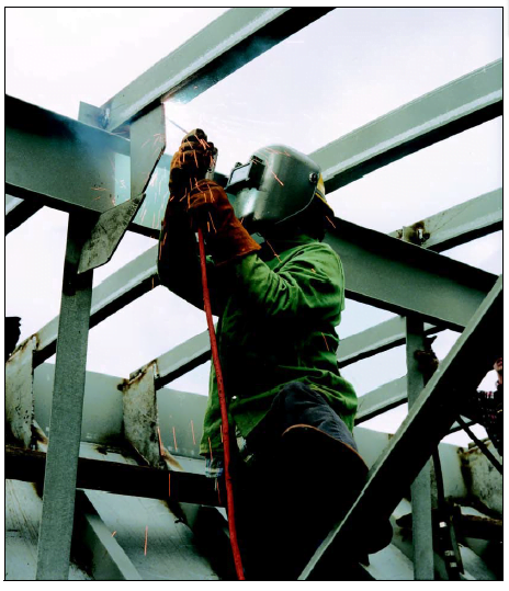
Shielded Metal Arc Welding (SMAW) — universally known as stick welding — is the most widely deployed manual arc welding process in the world. Defined under AWS A3.0 and referenced throughout ASME Section IX as one of the core welding processes, SMAW uses a consumable electrode coated in flux to generate an electric arc that melts both electrode and base metal, fusing them into a robust metallurgical joint. It remains the process of choice for field work, maintenance, structural fabrication, and position welding wherever portability, low cost, and versatility are paramount.
Despite competition from MIG/GMAW and TIG/GTAW in controlled shop environments, SMAW continues to dominate in pipeline field joints, structural steel erection, offshore construction, and repair welding — precisely because it requires no shielding gas supply, tolerates surface contamination better than gas-shielded processes, and functions reliably outdoors in adverse weather. This guide covers the entire SMAW process: historical development, operating principles, equipment, polarity, electrode classification and selection, welding positions, common defects and their prevention, safety requirements, and the code and standard requirements that govern its use in pressure equipment and structural applications.
Whether you are preparing for an AWS CWI examination, qualifying a welding procedure to ASME Section IX, or simply seeking a deeper technical understanding of the process, this guide provides the reference depth you need.
Historical Development of SMAW
The foundations of SMAW were laid in the second half of the 19th century through a series of pivotal discoveries in electric arc technology. In 1881, Auguste de Méritens demonstrated that a carbon arc could generate sufficient heat to fuse metals — the first practical arc-based joining method. Seven years later, Nikolay Slavyanov in Russia replaced the carbon electrode with a consumable metal electrode, creating what is recognisable as the precursor to modern arc welding and earning him recognition as the father of metal arc welding.
The limitation of bare metal electrodes — the unstable arc, atmospheric contamination, and brittle welds they produced — was addressed in the early 1900s. Arthur Percy Strohmenger in England and Oscar Kjellberg in Sweden independently developed coated electrodes in the period 1900–1907. Kjellberg’s calcium-silicate coated electrode, produced by his company ESAB (founded 1904), proved particularly effective and became the template for modern SMAW electrodes. The coating stabilised the arc and produced a slag blanket that protected the solidifying weld metal from oxygen and nitrogen pickup.
The interwar period brought significant industrial refinements. In 1927, the extrusion process for applying flux coatings was introduced, dramatically reducing electrode manufacturing costs and enabling tightly controlled coating composition. By the 1950s, iron powder was being added to low-hydrogen flux coatings, increasing deposition rates by up to 50% and enabling electrodes such as E7018 to become the workhorse of structural and pressure vessel fabrication. Specialised automated variants — gravity welding and firecracker welding — also emerged during this period for specific production applications.
SMAW Operating Principles
SMAW is classified as a constant current (CC) process. The welding power supply maintains an essentially constant current regardless of arc length fluctuations, which is essential for manual welding where the welder cannot maintain a perfectly uniform arc length. A self-regulating characteristic known as the volt-ampere drooping characteristic governs this: as arc length increases (voltage rises), current drops only slightly, preventing the arc from extinguishing; as arc length shortens, current rises only slightly, preventing violent spatter.
Arc Generation and Heat Transfer
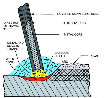
When the electrode tip makes contact with the base metal and is then withdrawn slightly, the current flows through the ionised gas column of the arc. Arc temperatures range from approximately 6,000 to 20,000 K — far exceeding the melting point of any engineering metal. This heat melts the electrode tip and a shallow pool of base metal simultaneously. The molten weld pool is protected from atmospheric oxygen and nitrogen by two mechanisms acting in concert:
- Gas shielding: Volatile components in the flux coating decompose to produce CO2, CO, and other gases that displace air around the arc and weld pool.
- Slag protection: The non-volatile components of the flux form a molten slag that floats on the weld pool, solidifying after the weld metal to form a rigid protective cover that must be chipped and brushed away after each pass.
Arc Initiation Techniques
Two arc-striking techniques are used in SMAW:
- Scratch start: The electrode is scratched across the base metal surface as though striking a match. This is fast but risks contaminating the weld start with electrode inclusions if the welder does not move forward promptly.
- Tap start: The electrode is brought perpendicular to the work, tapped lightly, and withdrawn to arc length. This is more controlled and is preferred for critical applications.
Once the arc is established, the welder maintains a consistent arc length — approximately equal to the electrode diameter — while progressing along the joint. Excessive arc length increases voltage, widens the bead, reduces penetration, and increases spatter; too short an arc risks stubbing (the electrode sticking to the base metal).
SMAW Circuit and Process Diagram
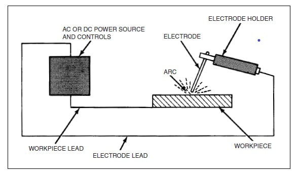
SMAW Equipment
The equipment required for SMAW is notably simple compared to gas-shielded processes, which is a key reason for its endurance in field and remote applications. The core system consists of four components.
Welding Power Supply
SMAW power supplies are constant current (CC) machines — also called drooping characteristic machines — that maintain a near-constant current over a range of arc voltages. This allows the welder to vary arc length without causing large current fluctuations, which would make manual welding impractical. Three types are available:
- Transformer (AC output): Lowest cost; produces alternating current. Suitable where AC electrodes are specified or where magnetic arc blow is a problem.
- Transformer-rectifier (DC output): Converts AC to DC, providing stable arc characteristics with the full range of electrode types. The most common shop machine.
- Inverter-based (DC output): Modern inverter technology produces extremely stable arcs, is lightweight and portable, and offers precise current control. Increasingly the preferred choice for field and pipeline applications.
Electrode Holder
The electrode holder grips the electrode at the correct angle and carries the welding current to the electrode. It must be fully insulated to protect the operator and rated for the maximum current to be used. The electrode clamp allows rapid changing of spent electrodes without tools.
Ground (Work) Clamp and Welding Cables
The ground clamp connects the return cable to the workpiece or welding table, completing the electrical circuit. Poor ground connections cause voltage drops, arc instability, and inconsistent weld quality. Cable cross-section must be appropriate for the welding current to prevent overheating; AWS D1.1 and general practice specify minimum cable sizes for given current ranges.
Welding Polarity in SMAW
Polarity selection in SMAW determines where the majority of the arc heat is concentrated and has a direct effect on penetration depth, deposition rate, and arc stability. Understanding polarity is essential for selecting the correct electrode and for qualifying welding procedures under ASME Section IX.
| Polarity | Connection | Heat Distribution | Penetration | Deposition Rate | Typical Electrode Types |
|---|---|---|---|---|---|
| DCEP (Direct Current Electrode Positive / Reverse Polarity) | Electrode to + terminal | ~2/3 at electrode, ~1/3 at work | Deep | Moderate | E7018, E7016, E6010, E6011 (most low-H electrodes) |
| DCEN (Direct Current Electrode Negative / Straight Polarity) | Electrode to − terminal | ~1/3 at electrode, ~2/3 at work | Shallow | Higher | E6020, some cellulosic types; useful for thin materials |
| AC (Alternating Current) | Alternates each half-cycle | Balanced (50/50 average) | Medium | Medium | E6011, E6013, E7024; used where DC arc blow is problematic |
SMAW Electrode Classification — AWS / ASME
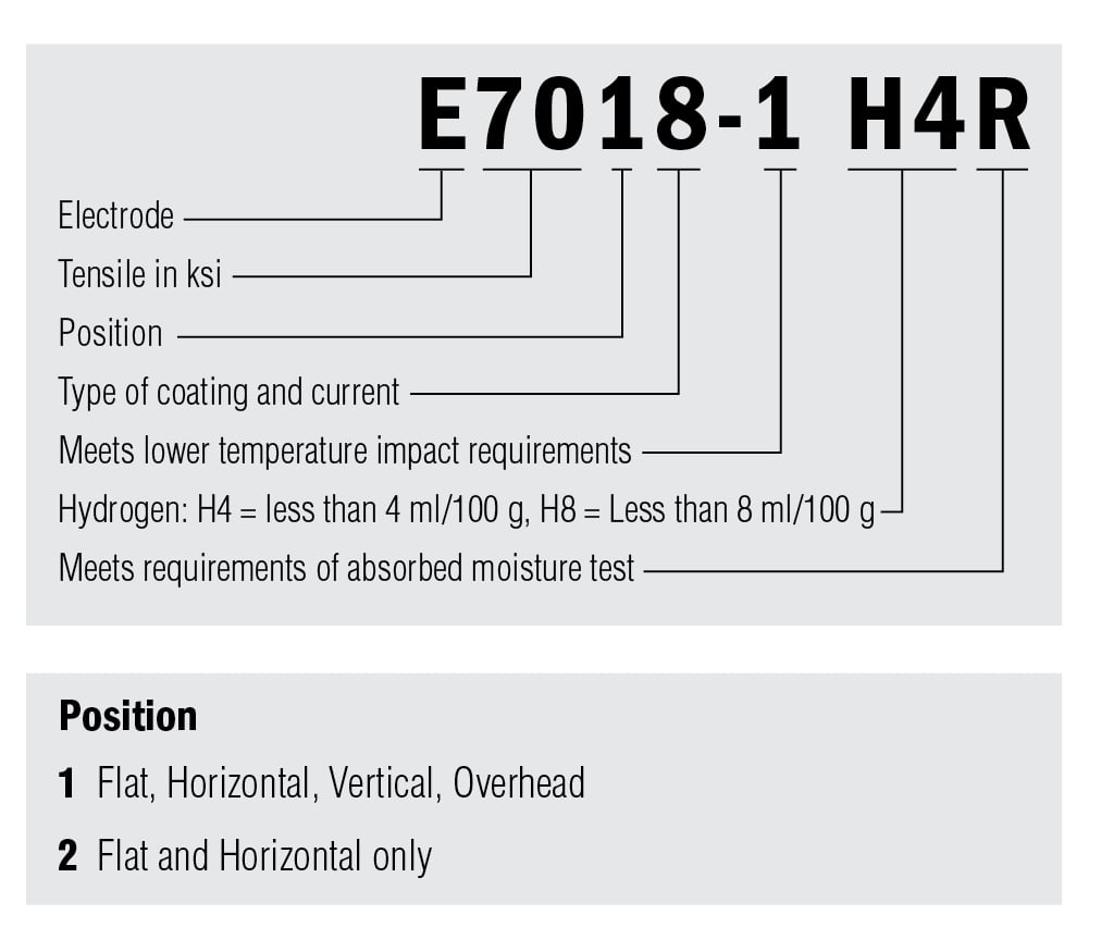
Electrode selection is arguably the most important variable in SMAW procedure specification. Electrodes are classified per AWS A5.1 (carbon steel) and AWS A5.5 (low-alloy steel) — both adopted by ASME as SFA-5.1 and SFA-5.5 respectively. The AWS classification system encodes five key parameters in the electrode designation.
E = Electrode
XX(X) = Minimum tensile strength in ksi (e.g., 70 = 70 ksi = 480 MPa)
Next digit = Welding positions: 1 = all positions
2 = flat and horizontal only
4 = flat, horizontal, vertical-down
Last digit = Flux coating + current type (see table below)
Example: E7018
70 ksi min. tensile (480 MPa) | All positions | Low-hydrogen, iron-powder, AC or DCEP
Last-Digit Coating and Current Reference (AWS A5.1)
| Last Digit | Flux Coating Type | Current / Polarity | Penetration | Key Characteristic |
|---|---|---|---|---|
| 0 | High cellulose, sodium | DCEP | Deep | E6010 — pipeline root passes, fast-freeze |
| 1 | High cellulose, potassium | AC or DCEP | Deep | E6011 — AC usable equivalent of E6010 |
| 2 | High titania, sodium | AC or DCEN | Medium | Smooth arc, good appearance |
| 3 | High titania, potassium | AC, DCEP, or DCEN | Medium | E6013 — easy-use, beginner-friendly |
| 4 | Iron powder, titania | AC, DCEP, or DCEN | Medium | E6014 — higher deposition fill-freeze |
| 5 | Low hydrogen, sodium | DCEP only | Medium | E7015 — low hydrogen, DC only |
| 6 | Low hydrogen, potassium | AC or DCEP | Medium | E7016 — low hydrogen, AC/DC |
| 7 | Iron powder, iron oxide | AC, DCEP, or DCEN | Medium | E7024 — high deposition, flat/horizontal |
| 8 | Low hydrogen, iron powder, potassium | AC or DCEP | Medium | E7018 — most common structural/pressure vessel electrode |
Electrode Groups: Fast-Fill, Fast-Freeze, Fill-Freeze
SMAW electrodes are also described by their solidification characteristics — a classification that guides position welding and deposition rate considerations:
- Fast-Fill electrodes (e.g., E7024, E7028): High iron-powder content; high deposition rates; best for flat and horizontal fillet welds where speed is the priority.
- Fast-Freeze electrodes (e.g., E6010, E6011): The weld pool solidifies rapidly, making these suitable for all-position welding including overhead and vertical-up. The preferred choice for pipeline root passes.
- Fill-Freeze electrodes (e.g., E6012, E6013, E7014): A balance of fill rate and rapid solidification, suitable for a wide range of positions and joint types — the general-purpose category.
Hydrogen Designators and Electrode Storage
For low-hydrogen electrodes (E7015, E7016, E7018 and equivalent), the AWS classification includes an optional hydrogen designator: H4R, H8, or H16 — indicating the maximum diffusible hydrogen level (4, 8, or 16 mL per 100 g weld metal) and whether the electrode has a moisture-resistant (R) coating. This is critical for welding on hardenable steels where diffusible hydrogen is the primary cause of hydrogen-induced cold cracking (HICC) in the HAZ.
SMAW Welding Technique and Parameters
Producing a sound SMAW weld requires control of five interdependent variables: current, arc length, travel speed, electrode angle, and electrode weave pattern. Each parameter interacts with the others, and the optimum combination depends on electrode type, material thickness, joint configuration, and welding position.
Welding Current
Current is the primary control variable for heat input. Too low a current produces an unstable arc, insufficient fusion, and slag inclusions; too high a current produces excessive penetration, undercutting, and overheating — particularly a risk on thin materials. Electrode manufacturers specify a recommended current range for each electrode diameter; these are reproduced on the electrode box and in the relevant SFA specification.
Heat input must be controlled within the PQR-qualified range for procedures
qualified to ASME Section IX or AWS D1.1
Example:
V = 24 V, I = 160 A, TS = 200 mm/min
HI = (24 x 160 x 60) / (200 x 1000)
HI = 1.15 kJ/mm
Arc Length
Arc length should be approximately equal to the electrode diameter (typically 2–4 mm for common electrode sizes). A long arc increases voltage, widens the bead, reduces penetration, allows atmospheric contamination, and — for low-hydrogen electrodes — increases the risk of hydrogen pickup by the weld metal. A short arc improves penetration and shielding but risks stubbing.
Electrode Angle
Two angles govern electrode orientation:
- Work angle: The angle between the electrode and the workpiece surface, measured perpendicular to the travel direction. For a flat butt weld, this is typically 90°. For a fillet weld, approximately 45° bisecting the joint angle.
- Travel angle (drag/push): The angle between the electrode axis and the vertical, in the direction of travel. SMAW is typically run with a 5–15° drag (backward lean), which directs arc force into the weld pool.
Welding Positions
SMAW can be performed in all standard welding positions. The AWS position designation system (referenced in ASME Section IX Table QW-461.3) classifies positions for groove welds as 1G (flat), 2G (horizontal), 3G (vertical), 4G (overhead), 5G (fixed pipe, horizontal axis), and 6G (fixed pipe, 45° inclined). Electrode type selection critically influences positional capability — fast-freeze electrodes such as E6010 are required for vertical-up and overhead; fast-fill electrodes such as E7024 are limited to flat and horizontal positions.
| Position | AWS Designation | Joint Type | Challenge Level | Electrode Type Needed |
|---|---|---|---|---|
| Flat | 1G / 1F | Groove / Fillet | Easiest | All types |
| Horizontal | 2G / 2F | Groove / Fillet | Easy | All types; fast-fill suitable |
| Vertical Up | 3G (up) / 3F | Groove / Fillet | Moderate | Fast-freeze (E6010, E6011, E7018) |
| Vertical Down | 3G (down) | Groove | Moderate | Specific downhill types (cellulosic); E6010 |
| Overhead | 4G / 4F | Groove / Fillet | Difficult | Fast-freeze only |
| Fixed Pipe (horiz. axis) | 5G | Groove (pipe) | Difficult | Fast-freeze; all-position electrodes |
| Fixed Pipe (45° inclined) | 6G | Groove (pipe) | Most challenging | Fast-freeze; all-position electrodes |
The welding positions guide on WeldFabWorld provides detailed diagrams for all positions and the corresponding ASME Section IX qualification ranges.
SMAW Electrode Construction — Cross-Section
Flux Coating Types and Their Metallurgical Effects
The flux coating is the defining variable in SMAW electrode performance. Different coating formulations produce fundamentally different arc characteristics, slag properties, weld bead profiles, and weld metal compositions. The five primary coating systems are:
| Coating Type | Primary Compound | Hydrogen Level | Arc Characteristics | Best Application |
|---|---|---|---|---|
| Cellulosic | Cellulose (organic) | High (>30 mL/100g) | Forceful, deep-penetrating arc | Pipeline root passes (E6010, E6011) |
| Rutile | TiO2 (titanium dioxide) | Medium (~15–30 mL) | Smooth, easy-control arc; fluid slag | General fabrication, thin steel (E6013) |
| Basic / Low-hydrogen | CaCO3 + CaF2 | Low (<10 mL, H4 grade <4 mL) | Moderate arc, stiff slag | Structural & pressure vessel (E7018) |
| Iron oxide | Fe2O3 | Medium | Fluid slag, flat bead | Fillet welds (E7024) — flat only |
| Iron powder addition | Fe powder in coating | Depends on base coating | High deposition rate | High-productivity flat welding (E7018, E7024) |
For more detail on electrode nomenclature and classification codes, see the welding consumable nomenclature guide.
Common SMAW Weld Defects and Prevention
Understanding defect formation mechanisms is the most practical route to prevention. Each SMAW defect has a specific metallurgical or procedural cause, and addressing the root cause — rather than simply adjusting one parameter — is key to consistent weld quality. See also the complete welding defects guide for inspection and acceptance criteria.
| Defect | Primary Causes | Prevention | Detection Method |
|---|---|---|---|
| Porosity | Moisture in electrode; surface contamination (oil, rust, paint); excessive arc length; damp base metal | Dry electrodes; clean base metal; maintain arc length; preheat damp material | RT, UT, VT (surface only for gross porosity) |
| Slag inclusions | Inadequate inter-pass slag cleaning; poor weld profile trapping slag; incorrect electrode angle | Thorough slag removal with chipping hammer and wire brush between passes; correct weave pattern | RT, UT |
| Incomplete fusion | Travel speed too fast; arc length too long; current too low; poor joint preparation | Increase current; slow travel speed; maintain correct arc length; correct joint geometry | RT, UT, MT (surface-breaking) |
| Undercut | Excessive current; too fast travel speed; incorrect electrode angle; long arc | Reduce current; slow travel; correct electrode angle; maintain proper arc length | VT, MT |
| Hydrogen-induced cracking (HIC) | Damp electrodes; insufficient preheat; high CE steel; high restraint joint | Use H4R or H8 electrodes from oven; apply preheat per CE; PWHT where required | MT, PT (delayed — inspect 24–48 h after welding) |
| Hot cracking | High sulfur base metal; concave bead profile (high tensile stress on solidifying weld); deep-narrow joint | Convex bead profile; correct current; use low-sulfur consumables; reduce restraint | VT, PT, MT |
| Spatter | Excessive current; arc blow; damp electrodes; too long arc length | Correct current; address arc blow; dry electrodes; maintain arc length | VT |
Safety in SMAW
SMAW presents a combination of electrical, thermal, optical, and chemical hazards that must be actively managed through engineering controls, administrative procedures, and personal protective equipment.
Electrical Safety
The open-circuit voltage (OCV) of SMAW power supplies typically ranges from 45 to 80 V — sufficient to cause a fatal electric shock, particularly in wet or humid conditions. All welding cables must be fully insulated and in good condition. The electrode holder must never be set down with a live electrode loaded. The welder must never change electrodes with bare hands; dry gloves must be worn at all times. In confined spaces, additional controls including isolation, residual voltage reduction, and continuous monitoring are required.
Arc Radiation and Eye Protection
The SMAW arc emits intense ultraviolet (UV) and infrared (IR) radiation. Unprotected exposure of even a fraction of a second can cause arc eye (photokeratitis), a painful condition equivalent to sunburn of the cornea. Welding helmets with lens shade DIN 9–13 (increasing with current level) are mandatory. Bystanders must be protected by opaque or UV-absorbing welding screens; translucent polycarbonate welding curtains reduce UV but do not fully replace the filter lens. For full PPE requirements, refer to the welding PPE guide.
Fume and Gas Control
SMAW generates fumes from the vaporised base metal, electrode coating, and surface coatings. Manganese fumes (from electrode and base metal) are of particular concern — chronic exposure causes manganism, a Parkinson’s-like neurological condition. Hexavalent chromium (Cr VI) fumes arise when welding on chromium-containing stainless steels. Engineering controls (local exhaust ventilation, LEV) are the primary control measure; respiratory protective equipment (RPE) — half-face or full-face powered air-purifying respirator — is required where LEV cannot achieve safe exposure levels. See the welding hazards and safety guide for full detail.
Applications and Materials
SMAW’s combination of portability, wide material capability, and low capital cost makes it the process of choice in a broad range of industries:
- Structural steel fabrication and erection — primary and secondary structural members per AWS D1.1
- Pressure vessel and boiler fabrication — butt joints, nozzle welds per ASME Section VIII and Section IX
- Petrochemical pipework — process piping per ASME B31.3; power piping per ASME B31.1
- Pipeline field joints — particularly root passes with cellulosic E6010 electrodes; fill and cap with E7018
- Maintenance and repair — where portability and tolerance of less-than-ideal surface conditions are essential
- Offshore and shipbuilding — structural and hull welds in outdoor environments where MIG shielding gas would be compromised by wind
Weldable Materials
SMAW can join a wide range of metallic materials with the correct electrode selection:
| Material Group | Electrode Series | Key Consideration |
|---|---|---|
| Carbon steel (P-1) | SFA-5.1 (E60xx, E70xx) | CE drives preheat; use low-H for t > 25 mm or CE > 0.40 |
| Low-alloy steel (P-3 to P-15) | SFA-5.5 (E70xx-x, E80xx-x etc.) | Match electrode composition to base metal; PWHT usually required |
| Stainless steel (P-8, P-10x) | SFA-5.4 (E308, E316, E309 etc.) | Control interpass temperature; use L-grade to prevent sensitisation |
| Nickel alloys (P-41 to P-47) | SFA-5.11 (ENiCrFe-x etc.) | Low heat input; strict interpass control; PWHT varies by grade |
| Cast iron | SFA-5.15 (ENiFe-CI, ENi-CI) | Preheat 300–600°C; slow cooling; butter layering technique |
| Copper alloys | SFA-5.6 (ECuSn-x, ECuAl-x) | High preheat needed; very limited use; GTAW preferred |
For stainless steel applications, refer to the guides on weld decay (sensitisation) and delta ferrite control. For sour service applications where hardness limits apply, see the sour service guide.
Advantages and Limitations of SMAW
Advantages
- Portable — no shielding gas, minimal auxiliary equipment
- Works outdoors in wind, rain, and adverse conditions
- Low equipment cost; simple setup
- Welds almost all ferrous and many non-ferrous alloys
- All positions possible with correct electrode selection
- Tolerates moderate surface contamination (rust, mill scale)
- Widely accepted by all major welding codes and standards
Limitations
- Lower deposition rates than GMAW or SAW
- Frequent electrode stub changes — reduces arc-on time
- Slag removal required between passes (time and labour)
- Minimum practical thickness approximately 1.5 mm
- Not easily automated
- Welder skill is the primary quality variable
- Higher hydrogen levels than TIG or MIG (especially cellulosic types)
For a direct process comparison, refer to the GMAW (MIG) guide, the GTAW (TIG) guide, and the submerged arc welding (SAW) guide.
Codes and Standards Governing SMAW
- ASME Section IX — Welding procedure and welder performance qualification for boiler and pressure vessel applications. SMAW is Process Number SMAW.
- AWS D1.1 — Structural Welding Code (Steel) — governs SMAW for structural applications including prequalified joint details.
- ASME B31.1 / B31.3 — Power and process piping codes; specify preheat, PWHT, and P-Number requirements for pipe welding.
- AWS A5.1 / ASME SFA-5.1 — Carbon steel covered arc welding electrodes.
- AWS A5.5 / ASME SFA-5.5 — Low-alloy steel covered arc welding electrodes.
- AWS A5.4 / ASME SFA-5.4 — Stainless steel covered arc welding electrodes.
- NACE MR0175 / ISO 15156 — Hardness and process requirements for sour (H2S) service, affecting electrode selection and PWHT.
Test your knowledge of ASME Section IX qualification requirements with the ASME Section IX practice quiz. For P-Number and F-Number classifications relevant to SMAW electrode selection, see the P-Number, F-Number and A-Number guide.
Recommended Reference Books
Disclosure: WeldFabWorld participates in the Amazon Associates programme (StoreID: neha0fe8-21). If you purchase through these links, we may earn a small commission at no extra cost to you. This helps support free technical content on this site.