Taper Transition for
Dissimilar Wall Thickness
— Complete Code Guide
When two components of different wall thicknesses are joined by welding, the abrupt change in section creates stress concentrations that can lead to premature fatigue failure. Taper transitions — governed by ASME Section VIII Div.1 UW-9, B31.1, and B31.3 — are the engineered solution. This guide covers when they are required, exactly how much taper is needed, how to fabricate them, the impact on PQR qualification, and what inspectors must verify.
What Is a Taper Transition?
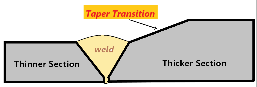
A taper transition is a gradual, tapered reduction of the thicker member’s section thickness, machined or ground to meet the thinner member at the weld joint. Rather than allowing an abrupt step at the weld, the taper distributes the load path smoothly between the two sections, reducing stress concentration factors at the junction.
The taper is created by removing material from the outside or inside surface (or both) of the thicker component — by machining, grinding, or a combination — over a defined minimum length. The resulting tapered surface is then welded to the thinner component in a standard butt joint configuration.
Why Is a Taper Transition Required?
The need for taper transitions is rooted in structural mechanics and fatigue theory. At any abrupt change in cross-section — such as the toe of a weld joining two plates of different thickness — several detrimental stress effects occur simultaneously:
At the junction of two dissimilar-thickness shells, the following effects are generated:
- Shear forces: The eccentric load path through the offset section creates transverse shear at the weld joint
- Bending moments: Offset of centrelines or surface planes produces secondary bending stresses superimposed on the primary membrane stresses
- Stress concentration: The geometric discontinuity amplifies the local stress — the stress concentration factor (Kt) at an abrupt step can be 2–4× the nominal membrane stress
- Fatigue damage acceleration: In cyclic service (pressure vessels under thermal cycling, piping under pulsating flow), elevated stress concentration dramatically shortens fatigue life
The taper transition eliminates the abrupt step by creating a gradual load path, redistributing the bending moment over the taper length, and bringing the stress field back toward the theoretical membrane stress — resulting in a shell structure with nearly constant strength across the joint.
Design principle: The purpose of the taper is not aesthetic — it is a structural requirement. A 1:3 minimum taper (1 unit rise over 3 units of length) is the engineering-code minimum needed to sufficiently reduce the stress concentration at the junction of dissimilar-thickness sections. In cyclic-service or fatigue-critical applications, steeper tapers (1:4 or longer) may be specified by the designer for additional safety margin.
When Is a Taper Transition Required?
Taper transition is not required for every dissimilar-thickness joint — codes provide a tolerance band within which a small thickness difference can be accommodated within the weld profile itself (using the weld bead as a gradual transition). The taper becomes mandatory when the thickness mismatch exceeds this tolerance.
(T₁ − T₂) > min(T₂/4 , 3 mm)
Quick-Reference Trigger Decision Table
| T₁ (Thick, mm) | T₂ (Thin, mm) | Offset y (mm) | T₂/4 (mm) | Trigger Limit = min(T₂/4, 3mm) | y > Limit? | Taper Required? |
|---|---|---|---|---|---|---|
| 12 | 10 | 2 | 2.5 | 2.5 | No (2 < 2.5) | No — within tolerance |
| 14 | 10 | 4 | 2.5 | 2.5 | Yes (4 > 2.5) | YES — taper required |
| 20 | 14 | 6 | 3.5 | 3.0 | Yes (6 > 3.0) | YES — taper required |
| 25 | 20 | 5 | 5.0 | 3.0 | Yes (5 > 3.0) | YES — taper required |
| 16 | 14 | 2 | 3.5 | 3.0 | No (2 < 3.0) | No — within tolerance |
| 50 | 38 | 12 | 9.5 | 3.0 | Yes (12 > 3.0) | YES — taper required |
Note on the “lesser of” rule: Once T₂ exceeds 12 mm, T₂/4 will always be greater than 3 mm — so for most practical pressure vessel thicknesses, the trigger condition simplifies to: taper required if y > 3 mm. For thin-wall applications (T₂ < 12 mm), T₂/4 may govern instead — always check both conditions.
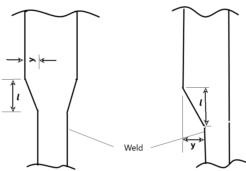
How Much Taper Is Required? — The 1:3 Rule
Once a taper transition is required, the minimum taper ratio is specified by code. ASME Section VIII Div.1 UW-9(c) mandates a minimum taper of 1:3 — meaning for every 1 unit of height (offset y) being tapered away, the taper must extend at least 3 units in length.
Worked Calculation Examples
Example 1 — Shell Plate Joint (Original Code Example)
Two pressure vessel shell plates of 20 mm and 14 mm thickness are to be joined by a butt weld. Determine if a taper transition is required, and if so, calculate the minimum taper length.
T₁ = 20 mm (thick member), T₂ = 14 mm (thin member)
y = T₁ − T₂ = 20 − 14 = 6 mm
T₂/4 = 14/4 = 3.5 mm | 3 mm (fixed limit)
Trigger limit = min(3.5, 3.0) = 3.0 mm
y = 6 mm > 3.0 mm → Taper REQUIRED ✔
l ≥ 3y = 3 × 6 = 18 mm minimum
Example 2 — Pipe-to-Flange Connection
A DN200 Schedule 80 pipe (wall thickness = 12.7 mm) is to be welded to a flange with a bore wall thickness of 18 mm. Is a taper transition needed?
T₁ = 18 mm (flange bore), T₂ = 12.7 mm (pipe wall)
y = 18 − 12.7 = 5.3 mm
T₂/4 = 12.7/4 = 3.175 mm | 3 mm limit
Trigger = min(3.175, 3.0) = 3.0 mm
y = 5.3 mm > 3.0 mm → Taper REQUIRED ✔
l ≥ 3 × 5.3 = 15.9 mm → Round up to 16 mm minimum
The flange bore must be bored/machined internally over a minimum 16 mm length from the weld face.
Example 3 — Small Offset Within Tolerance (No Taper)
A shell plate of 16 mm is welded to a 14 mm plate. Is a taper required?
y = 2 mm < 3.0 mm → No taper required ✔
How to Form a Taper Transition — Fabrication Methods
The taper can be formed by three methods, which may be used individually or in combination, depending on the joint geometry, material, and whether the offset is on the inside diameter (ID), outside diameter (OD), or both surfaces:
✅ OD Taper (Outside Surface)
- Most common and accessible method
- Applied to plate, shell, and head components
- Machined before welding or ground after fit-up
- Easy to inspect dimensionally and visually
- Does not affect internal bore dimensions
✅ ID Taper (Inside Surface / Bore)
- Required when OD taper not feasible (nozzle connections)
- Applied by boring, grinding, or turning the internal bore
- Critical for pipe-to-flange and nozzle-to-shell joints
- Must be accessible for dimensional check by gauge or UT
- Flow considerations must be checked (reduced bore)
Weld build-up as taper method: The taper may also be achieved by depositing additional weld metal to build up the thinner member to a tapered profile — where a weld build-up of the appropriate slope is deposited on the thinner section before the final joint weld is made. This method is particularly useful when machining access is limited. The build-up must be qualified under the applicable procedure and meet the same dimensional requirements (l ≥ 3y).
Taper Requirements Across ASME Codes
While ASME Section VIII Div.1 UW-9 is the most cited reference, taper transition requirements also appear in the pressure piping codes and with slightly different language. The underlying engineering requirement is the same — a gradual transition to avoid stress concentration — but the trigger conditions and references differ:
Pressure Vessels
- Taper required when y > min(T₂/4, 3 mm)
- Minimum taper: l ≥ 3y (1:3 ratio)
- Applies to all shell butt joints of unequal thickness
- Taper may be on OD, ID, or both surfaces
- May be formed by machining, grinding, or weld build-up
Power Piping
- Similar trigger: offset exceeding ¼ thinner wall or 1.6 mm (1/16″) whichever is less for some cases
- Minimum 1:3 taper angle required from weld joint surface
- Applies to butt welds in pressure piping systems
- Taper dimension measured from the weld prep face
- Check current edition for exact threshold language
Process Piping
- Addresses weld joint mismatch and offset requirements
- Requires taper when offset exceeds ¼ of the thinner component thickness or 1.6 mm whichever is less for butt welds
- 1:3 minimum taper from inside or outside surface
- Provides additional guidance for shop vs. field joints
- Check current edition for exact limits and figures
Structural Welding (Steel)
- Structural welds with thickness transitions require a 1:2.5 minimum taper in some configurations
- Exact requirements depend on joint type (CJP butt welds)
- Fatigue category affected by presence/absence of taper
- Smoother tapers (>1:4) may be required for higher fatigue categories
- Different from pressure vessel requirements — always verify applicable code
Always use the code applicable to your component: The taper transition requirements in ASME VIII are not automatically interchangeable with B31.1 or B31.3 piping codes. Each code edition may have slightly different threshold values and figure references. Always verify against the current applicable edition and any project-specific supplementary requirements or client specifications.
Procedure Qualification Requirements — ASME Section IX QW-202.3
When a welding procedure is qualified using a test coupon that includes a taper transition at the weld, specific rules govern the qualified thickness range and test specimen preparation under ASME Section IX QW-202.3:
QW-202.3 Rule: When the thicker test coupon is tapered to provide a transition at the weld, the qualified range shall be based on the base metal thickness adjacent to the toe of the weld at the thinnest end of the transition — not the full thickness of the thicker plate. The test specimens for tensile and bend tests may be machined to the thickness required for the thinner base metal prior to testing.
This rule has important practical implications for procedure qualification on projects involving dissimilar thickness joints:
| Situation | Qualified Thickness Basis | Practical Implication |
|---|---|---|
| Test coupon tapered at the weld | Based on thickness at toe of weld — thinnest end of taper | The 20 mm plate tapered to 14 mm at the weld = qualified range based on 14 mm, not 20 mm |
| Test specimen machining | May be machined to thinner base metal thickness before testing | Tensile and bend specimens machined to 14 mm — simpler tooling, avoids bend test issues with thick specimens |
| Qualified thickness range | Per QW-451 ranges applied to the thinnest weld toe thickness | Ensure the taper-qualified PQR covers the production joint thin-member thickness — may need separate PQR for wider range |
| Taper omitted on production welds | Full T₁ thickness governs | PQR without taper must qualify the full T₁ range — a taper-qualified PQR is not automatically valid for untapered joints of T₁ thickness |
Fabrication Quality Control & Inspection Requirements
Taper transitions must be verified during fabrication by the welding inspector as part of the pre-weld, in-process, and post-weld inspection checklist. The following items must be checked:
🔍 Inspector Checklist — Taper Transition Verification
Common Mistakes & Non-Conformances
| Non-Conformance | Root Cause | Consequence | Prevention |
|---|---|---|---|
| Taper not applied when required | Drafter or fabricator unaware of code trigger; thickness mismatch not identified at fit-up | Stress concentration at weld; potential fatigue failure in service; code non-compliance | Pre-weld inspector check of both part thicknesses; drawing review |
| Taper length insufficient (l < 3y) | Incorrect calculation; grinding stopped early; drawing error | Insufficient load distribution; non-conformance on dimensional inspection | Calculate required l before machining; inspect with gauge after grinding |
| Abrupt steps or tool marks left on taper surface | Poor grinding technique; inadequate finishing pass | Local stress concentration at grinding marks; potential fatigue crack initiation | Finish grind smooth; inspect with straight-edge; consider PT/MT on taper zone |
| PQR qualification basis incorrect under QW-202.3 | PQR qualified to full T₁ range but taper-toe governs qualified range | Production weld outside qualified thickness range — procedural non-conformance | Identify taper-toe thickness at PQR stage; apply QW-451 ranges to taper-toe T value |
| Wrong surface selected for taper | Taper applied to OD when ID offset governs (e.g., bore mismatch) | External appears conforming; internal step creates stress and potential crevice | Identify which surface has the offset and apply taper to that surface |
| NDT misses taper zone thickness variation | UT calibrated for uniform thickness; RT exposure not adjusted for taper | Inadequate examination sensitivity in the taper zone; defects may be missed | Plan NDT technique to account for variable thickness; multi-exposure RT or PAUT |
🎯 Test Your ASME Code Knowledge
Taper transition, essential variables, and joint design questions appear regularly in ASME and CSWIP exams. Practice with our free quizzes.
Key Takeaways
| Question | Answer |
|---|---|
| What is a taper transition? | Gradual removal of material from the thicker member to match the thinner section at the weld joint, creating a smooth load path. |
| When is it required (ASME VIII)? | When offset y = T₁ − T₂ exceeds the lesser of T₂/4 or 3 mm. |
| What is the minimum taper? | l ≥ 3y (1:3 ratio minimum) per ASME Section VIII Div.1 UW-9(c). |
| Why is it required? | To reduce shear and bending moment at the section change, minimising stress concentration and producing near-constant structural strength. |
| How is it formed? | By machining, grinding, or weld build-up on the OD, ID, or both surfaces. |
| PQR qualification impact? | Per QW-202.3, qualified thickness range is based on the taper-toe (thinnest weld end) thickness, not the full T₁ of the thicker plate. |
| Other applicable codes? | ASME B31.1, B31.3 (process and power piping), AWS D1.1 (structural steel) — each with slightly different trigger thresholds. |