Preheat in Welding — Everything You Need to Know
Preheat in welding is one of the most cost-effective and metallurgically powerful interventions available to a fabricator. By raising the base metal to a controlled temperature before the first arc is struck, you slow down the cooling rate of the weld and heat-affected zone (HAZ), dramatically reducing the risk of hydrogen-induced cold cracking, excessive hardness, and residual stress build-up. Whether you are welding low-alloy pressure vessels to ASME codes or structural steel to AWS D1.1, a correct preheat strategy is often the single factor that separates a sound weld from a rejected one.
This article covers the complete picture: the metallurgical reasons why preheat works, the four factors that drive preheat temperature selection, how to calculate the minimum preheat using carbon equivalent, code-specific requirements from ASME, AWS, and API, proper measurement technique, and the equally important concept of interpass temperature. You will also find worked examples, preheat tables for common materials, and answers to the most frequently asked questions.
If you want to go deeper on carbon equivalent — the central input to any preheat calculation — visit the Carbon Equivalent (CE) Calculator and Complete Guide on WeldFabWorld.
The Metallurgy Behind Preheating
When a weld pool solidifies on a cold base metal, the surrounding material acts as a heat sink. The steep temperature gradient produces a rapid cooling rate through the critical transformation range (roughly 800 °C to 500 °C). For hardenable steels — anything with appreciable carbon, manganese, chromium, molybdenum, or vanadium — rapid cooling promotes the formation of martensite, a hard, brittle microstructure that is extremely susceptible to cracking when hydrogen is present.
Preheat addresses this in four distinct ways simultaneously. First, it reduces the temperature differential between the weld deposit and the base metal, slowing the cooling rate. Second, it extends the time the joint spends above the temperature at which hydrogen diffusion is active (roughly 150 °C and above), allowing hydrogen to escape before it can cause damage. Third, it reduces the yield strength of the base metal slightly, which means thermal stresses generated by cooling are partially accommodated by plastic deformation rather than stored as locked-in residual stress. Fourth, for thick sections, it ensures proper fusion penetration by raising the starting temperature of the base metal.
When Is Preheat Required?
Preheat is not always mandatory, but it is required — either by code or by sound engineering judgment — under the following conditions:
- High carbon equivalent (CE > 0.40–0.45): steels with elevated carbon and alloying content harden rapidly on cooling.
- Thick sections: greater thickness means faster heat extraction and more restraint. Preheat requirements increase with wall thickness.
- High hydrogen consumables: cellulosic electrodes or wet, poorly stored consumables introduce hydrogen into the weld pool.
- High restraint joints: heavily restrained configurations (nozzle-to-shell, set-on branch connections) concentrate stress at the weld root.
- Cold ambient conditions: base metal below 10 °C accelerates cooling dramatically; most codes require preheat to at least 10 °C for common steels even before thickness-based requirements apply.
- Brittle base materials: cast iron, hardened tool steels, and some high-alloy grades are extremely notch-sensitive and require careful preheat management.
- Post-weld heat treatment (PWHT) deferral: when PWHT cannot be performed immediately, a hydrogen bake-out (hold at 200–300 °C for 2–4 hours) is frequently specified as an interim measure.
The Four Factors That Control Preheat Temperature
1. Carbon Equivalent (CE)
The carbon equivalent translates the combined effect of all alloying elements on hardenability into a single number. The IIW (International Institute of Welding) formula, used as the basis for most code preheat tables, is:
CE = C + Mn/6 + (Cr + Mo + V)/5 + (Ni + Cu)/15
All element contents in weight percent, taken from the mill test certificate
Example:
ASTM A516 Gr.70 (typical): C=0.23, Mn=1.20, Cr=0, Mo=0, V=0, Ni=0, Cu=0
CE = 0.23 + 1.20/6 = 0.23 + 0.20 = 0.43
CE = 0.43 — Preheat consideration required for thick sections and high-hydrogen processes
An alternative formula used for microalloyed steels (Pcm — Process Chemistry Method or Ito-Bessyo formula) is better suited for low-carbon, high-strength steels:
Pcm = C + Si/30 + (Mn+Cu+Cr)/20 + Ni/60 + Mo/15 + V/10 + 5B
Preferred for C < 0.18% and low-alloy high-strength steels
Use the WeldFabWorld Carbon Equivalent Calculator to compute CE from your mill certificate values instantly.
2. Section Thickness
Thickness governs the rate at which heat is extracted from the weld joint. A thin plate dissipates heat slowly in two dimensions; a thick plate or heavy fitting extracts heat rapidly in three dimensions. Codes typically step up preheat requirements at defined thickness bands — for example, AWS D1.1 specifies preheat in increments across four thickness ranges: up to 19 mm, 19–38 mm, 38–65 mm, and over 65 mm.
3. Hydrogen Content (HD)
The diffusible hydrogen content of the weld metal, measured in mL per 100 g of deposited metal (mL/100g), directly influences the preheat requirement. As-received basic low-hydrogen electrodes properly dried to manufacturer specification typically produce < 5 mL/100g. Moisture-contaminated or cellulosic electrodes can produce 15–30 mL/100g or more. AWS A4.3 classifies diffusible hydrogen into five bands: H4, H8, H16, H32, and no designation (>32 mL/100g).
4. Degree of Restraint
Even at identical CE and thickness values, a nozzle-to-shell weld is vastly more restrained than a free butt weld on a bench. Restraint concentrates residual tensile stress at the weld root and toe, lowering the threshold at which hydrogen cracking initiates. The restraint factor is the most difficult to quantify but is addressed qualitatively in most fabrication standards through the requirement to increase preheat for “highly restrained joints.”
Minimum Preheat Temperature Guide by Material Group
| Material / P-Number | Typical CE Range | Thickness ≤ 25 mm | Thickness 25–50 mm | Thickness > 50 mm | Code Basis |
|---|---|---|---|---|---|
| C-Mn Steel (A516, A105) — P1 | 0.35–0.50 | None – 10 °C | 80–100 °C | 100–150 °C | AWS D1.1 / ASME B31.3 |
| 1¾ Cr ½ Mo Steel (A387 Gr.11) — P4 | 0.55–0.70 | 150 °C | 175 °C | 200 °C | ASME VIII / B31.3 |
| 2¼ Cr 1 Mo Steel (A387 Gr.22) — P5A | 0.70–0.90 | 175 °C | 200 °C | 230 °C | ASME VIII / B31.3 |
| 9Cr-1Mo-V (P91, A335 Gr.P91) — P5B | N/A (Pcm based) | 200 °C min | 200 °C min | 200 °C min | ASME / EPRI Guidelines |
| Austenitic SS (304, 316) — P8 | N/A | None | None | None | Max interpass only |
| Duplex SS (P91/2205) — P10H | N/A | None | None | None | Max interpass 150 °C |
| Cast Iron (all grades) | High CE | 150–200 °C | 200–300 °C | 300–400 °C | Manufacturer / WPS |
Benefits of Preheating — Engineering Detail
Preventing Hydrogen-Induced Cold Cracking (HICC)
HICC — also called delayed cold cracking, underbead cracking, or hydrogen-assisted cracking (HAC) — is the dominant failure mode that preheat is designed to prevent. It requires three conditions to occur simultaneously: a susceptible (hard, martensitic) microstructure, sufficient hydrogen in the weld zone, and tensile stress above a threshold. Preheat directly addresses two of these three: it reduces hardness by slowing cooling (attacking the susceptible microstructure), and it drives out hydrogen by keeping the joint above the diffusion threshold for longer.
Importantly, HICC is “cold” cracking — it typically initiates below 200 °C and may not appear until hours or even days after welding. This makes it particularly dangerous in fabrication inspection scenarios where the weld may appear sound immediately after deposition. For pressure equipment, this is the reason that post-weld NDE (often MT or UT) is frequently delayed 24–48 hours after welding on materials with CE > 0.45.
Stress Reduction and Distortion Control
The contraction of a cooling weld deposit is constrained by the surrounding cold base metal, which stores the incompatibility as residual tensile stress at the weld toe and root — precisely where fatigue and stress-corrosion cracking initiate in service. Preheat reduces the temperature differential between the weld and the base metal, which proportionally reduces the differential contraction strain and thus the residual stress. For highly restrained joints such as set-on nozzles, this benefit can be as important as the crack-prevention benefit.
Improved HAZ Toughness
The coarse-grained HAZ (CGHAZ) immediately adjacent to the fusion boundary is the microstructurally damaged zone where transformation products other than those in the original heat-treated base metal form. Preheat, by reducing hardness (and therefore reducing martensite fraction in the CGHAZ), directly improves toughness. For applications requiring low-temperature impact testing under ASME Section VIII UG-84, this is a critical consideration.
Penetration and Fusion in Thick Sections
On sections above approximately 50 mm, a significant fraction of the welding heat input is extracted by the mass of cold base metal before it achieves fusion at the root. Preheating reduces this heat loss and allows the same arc energy to achieve better root penetration. This is also why preheat is specified in thermal cutting operations on high-CE steels — cold base metal causes edge hardening and cracking in oxy-fuel and plasma-cut profiles.
How to Measure Preheat Temperature
Three methods are used in fabrication shops and field construction:
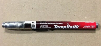
Temperature-Indicating Sticks (Tempilstik)
Temperature-indicating crayons (Tempilstik, Markal Thermomelt) are solid sticks that melt at a specific calibrated temperature. The welder draws a mark 75 mm from the weld centreline; when the mark melts and turns shiny, the target temperature has been reached. They are inexpensive, simple, and require no calibration. However, they only confirm that the minimum temperature has been reached — they cannot tell you the actual temperature above the threshold or show temperature gradients across the joint.
Contact Thermometers (Digital Pyrometers)
Calibrated digital contact thermometers with K-type thermocouples provide a continuous, accurate temperature reading. They are the most reliable method for audit-trail documentation in code-critical work. Calibration records must be maintained and traceable to a national standard.
Infrared (IR) Non-Contact Thermometers
Infrared guns are fast, non-contact, and suitable for measuring temperature distribution across a large preheated area. Their main limitation is emissivity sensitivity — a shiny, freshly ground weld surface has a very different emissivity from an oxidised plate surface, which can introduce significant reading errors. Always verify IR readings against a contact thermometer on the specific surface you are measuring, and apply an emissivity correction factor.
Interpass Temperature — The Other Side of the Coin
While preheat specifies a minimum temperature, interpass temperature specifies the maximum temperature permitted between weld passes. Exceeding the maximum interpass temperature can cause:
- Excessive grain growth in the HAZ, reducing toughness
- Sensitisation of austenitic stainless steels (chromium carbide precipitation at grain boundaries — see the guide to weld decay)
- Overaging or softening of precipitation-hardened alloys
- Unacceptable delta ferrite reduction in duplex and austenitic stainless welds — see the delta ferrite guide for why this matters
- Degradation of Charpy impact properties in fine-grained structural steels
| Material | Min Preheat | Max Interpass | Note |
|---|---|---|---|
| C-Mn / Low-Alloy Steel (P1) | As required by CE and thickness | 250 °C (typical) | Check WPS for specific value |
| Cr-Mo Steel P4 / P5 | 150–200 °C | 300–350 °C | ASME B31.3 / Code case |
| P91 (9Cr-1Mo-V) | 200 °C | 300 °C | Critical: narrow window |
| Austenitic SS (304L/316L) | None | 175 °C (per WPS) | Sensitisation prevention |
| Duplex SS (2205) | None | 150 °C | Ferrite balance critical |
| Nickel Alloys (Inconel 625) | None | 150 °C | Refer to SFA-5.14 WPS |
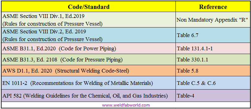
Preheat Requirements Under Key Codes and Standards
ASME Section IX — Welding Procedure Qualification
QW-406 of ASME Section IX covers preheat as a welding variable. A decrease of more than 55 °C (100 °F) below the qualified preheat temperature is an essential variable for P-numbers 1, 3, 4, 5A, 5B, and 5C, requiring a new procedure qualification. For supplementary essential variables (where impact testing applies), even smaller changes may require re-qualification. The actual preheat values for ASME pressure vessels are given in ASME Section VIII Division 1 Appendix R and in B31.3 Table 330.1.1 for piping.
AWS D1.1 — Structural Welding Code (Steel)
Table 4.2 of AWS D1.1:2020 specifies minimum preheat and interpass temperatures for four categories of weld metal and base metal combinations across four thickness ranges. The categories (Category A through D) are broadly ordered by CE and yield strength. The code also requires preheat whenever base metal temperature is below 0 °C (32 °F), regardless of other conditions.
API 582 / API RP 934-A — Refinery and Petrochemical
API 582 provides recommended preheat practices for carbon steel, low-alloy steel, and CrMo steels used in refining equipment. API RP 934-A specifically addresses heavy-wall Cr-Mo vessels and is the primary reference for P22 (2¼Cr-1Mo) and P91 welding in the petrochemical industry.
Methods of Applying Preheat
Oxy-Fuel Torch Heating
The most flexible and widely used method for small to medium fabrications. An oxy-acetylene or oxy-propane torch is moved in a sweeping motion across the joint. The heat must be applied on the side opposite to welding where possible, and care must be taken not to overheat localised areas, which can cause local phase transformation or surface oxidation that compromises fusion quality.
Electrical Resistance Heating
Ceramic-pad resistance heaters wrapped around the joint with insulating blankets are the preferred method for field piping and vessel nozzle work, particularly for P91 and high-alloy steels. They provide even, controllable heat distribution and can be thermostatically controlled. They also double as post-weld heating devices for hydrogen bake-outs and controlled cool-downs after welding on sensitive materials.
Induction Heating
Induction coils generate heat within the steel itself through electromagnetic induction. This method heats the material from the inside out, giving excellent temperature uniformity through the wall thickness — critical for thick-wall headers and nozzles on power plant boilers. Induction is particularly recommended for P91 preheat and PWHT because of the superior through-thickness uniformity.
Furnace Preheating
For small to medium components that can be shop-fabricated, furnace preheat is the most controlled and uniform method. Entire weldments are brought to temperature before moving to the welding station. This is standard practice for cast iron repair and for high-alloy reactor vessels where contamination from torch heating cannot be tolerated.
Recommended Reading on Welding Metallurgy and Preheat
Disclosure: WeldFabWorld participates in the Amazon Associates programme (StoreID: neha0fe8-21). If you purchase through these links, we may earn a small commission at no extra cost to you. This helps support free technical content on this site.