Guide to Dye Penetrant Testing (DPT) in Welding & NDT
Dye penetrant testing (DPT) — also known as liquid penetrant inspection (LPI or PT) — is one of the oldest and most widely used methods in non-destructive testing (NDT). Whether you are inspecting a weld on a pressure vessel, checking a turbine blade in an overhaul shop, or qualifying a piping butt joint to ASME Section IX, liquid penetrant examination offers a fast, reliable, and cost-effective route to detecting surface-breaking discontinuities across virtually every non-porous engineering material.
Unlike magnetic particle inspection (MPI), DPT places no restriction on material type — it works equally well on ferrous metals, austenitic stainless steels, aluminium, titanium, nickel alloys, ceramics, and plastics. The governing ASME standard is Section V, Article 6; the parallel ASTM document is ASTM E165. Both specify required procedure elements, qualification of personnel, lighting conditions, and acceptance criteria. This guide walks you through the complete process in the precise sequence demanded by these codes, together with the technical reasoning behind every step.
You will also find penetrant classification tables, dwell-time guidance, developer selection rules, SVG process schematics, acceptance-criteria reference data, and a comprehensive FAQ section — everything required to understand DPT from first principles and apply it confidently in a fabrication or maintenance environment.
Penetrant Testing Process Overview
The physical mechanism behind penetrant testing is capillary action — the same force that draws water up through a narrow glass tube or a plant’s root system. When a low-viscosity, low-surface-tension penetrant liquid is applied to a clean surface, it is drawn into any open discontinuity by the pressure differential created between the liquid film and the trapped air inside the defect. The tighter and finer the defect, the longer the dwell time required for the penetrant to fully occupy it.
Penetrant Classification and Selection
Penetrants are classified by two independent criteria: Type (based on the dye used) and Method (based on how the excess penetrant is removed). Choosing the correct combination is not optional — it is a procedural requirement under ASME Section V Article 6 and must be documented in the written Liquid Penetrant Examination Procedure (LPEP).
Penetrant Type
| Type | Dye | Inspection Light | Min. Light Intensity | Sensitivity | Typical Application |
|---|---|---|---|---|---|
| Type I | Fluorescent | UV-A (365 nm) | 1,000 µW/cm² | High | Aerospace, nuclear, critical pressure vessels |
| Type II | Visible (colour-contrast) | White / visible light | 100 fc (1,100 lux) | Moderate | Field welding, piping, general fabrication |
| Type III | Dual (fluorescent + visible) | UV-A or white light | As applicable | High | Inspection of in-service components (less common) |
Penetrant Method (Removal Technique)
| Method | Removal Agent | Sensitivity Level | Pros | Cons |
|---|---|---|---|---|
| Method A Water-Washable | Water rinse | Level 1–2 | Fast, low cost, field portable | Risk of over-washing, lower sensitivity |
| Method B Lipophilic Post-Emulsifiable | Oil-based emulsifier + water | Level 3–4 | High sensitivity, process control | Extra emulsifier step, time critical |
| Method C Solvent Removable | Solvent-dampened cloth | Level 2–3 | Portable, suitable for small areas | Slow for large areas, solvent waste |
| Method D Hydrophilic Post-Emulsifiable | Water-based emulsifier + water | Level 4 (highest) | Maximum sensitivity | Requires spray booth, highest cost |
Penetrant Sensitivity Levels
ASTM E1417 defines five sensitivity levels for fluorescent penetrants (Type I): Level 1/2 (ultra-low) through Level 4 (ultra-high). These correspond to the minimum detectable crack width and depth. The sensitivity level required for a given inspection is specified in the applicable code, drawing, or quality plan. Higher sensitivity levels require stricter surface preparation, longer dwell times, and more controlled removal conditions.
| Level | Description | Typical Application |
|---|---|---|
| Level 1/2 | Ultra-low | Rough castings, preliminary checks |
| Level 1 | Low | General fabrication, structural steelwork |
| Level 2 | Medium | Pressure vessel welds, most industrial applications |
| Level 3 | High | Safety-critical aerospace and nuclear components |
| Level 4 | Ultra-high | Turbine blades, primary nuclear pressure boundary |
The Six-Step Penetrant Testing Procedure in Detail
The six steps below follow the mandatory sequence defined in ASME Section V, Article 6 and ASTM E165. Each step must be completed in order — skipping or combining steps compromises result reliability and is a non-conformance under most quality management systems.
Pre-Cleaning
The test surface and any surrounding area must be free from all contamination that could either prevent penetrant entry into a defect or produce a misleading indication. Contaminants of concern include paint, scale, oil, grease, weld spatter, pickling residues, and corrosion products. Cleaning methods include solvent wiping, alkaline detergent cleaning, vapour degreasing, ultrasonic cleaning, and abrasive or media blasting.
One critical caution: if media blasting is used, the abrasive can peen over the mouths of fine cracks, sealing them and making them undetectable. ASTM E165 therefore recommends an acid etching step after blasting to re-open any peened crack mouths before applying penetrant. After cleaning, the surface must be completely dry before the penetrant is applied — any residual moisture will prevent penetrant entry.
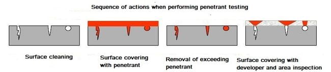
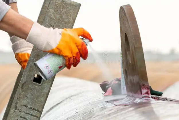
Application of Penetrant and Dwell Time
The penetrant is applied to cover the entire examination surface by spraying from an aerosol can, brushing, or dipping the component in a penetrant bath. The penetrant must remain wet on the surface for the entire dwell period — the surface must not be allowed to dry. Once applied, the penetrant requires a minimum dwell (contact) time to migrate into all open discontinuities by capillary action.
Dwell times are specified in the written procedure and must be based on the penetrant manufacturer’s recommendations combined with applicable code requirements. The table below provides general guidance from ASTM E165:
| Material / Defect Type | Min. Dwell Time (min) | Max. Dwell Time (min) |
|---|---|---|
| Aluminium, magnesium — castings (porosity, cold shuts) | 5 | 30 |
| Carbon steel, low-alloy steel — welds (cracks, lack of fusion) | 10 | 60 |
| Stainless steel — welds and base metal | 10 | 60 |
| Nickel alloys, titanium — tight fatigue cracks | 30 | 120 |
| Plastics, ceramics | 5 | 30 |
Excess Penetrant Removal
This is the most technique-sensitive step in the entire process. The objective is to remove all penetrant from the surface without removing it from inside the defects. The removal method must match the penetrant method as classified above — using the wrong removal agent can either contaminate the system or strip penetrant from the flaws.
For Method C (solvent removable) penetrant, the correct technique is as follows: first, wipe the bulk of the penetrant from the surface using dry lint-free cloths. Then, lightly dampen a fresh lint-free cloth with solvent and wipe the surface clean using consistent strokes in one direction. Under no circumstances should solvent be sprayed directly onto the examination surface — this will flush penetrant out of the defects and destroy the sensitivity of the examination.
For Method A (water-washable) penetrant, a water spray (coarse drops, not a fine mist) at a pressure not exceeding 40 psi (275 kPa) and temperature between 10°C and 38°C is used. Over-rinsing is the primary risk — it removes penetrant from open, shallow defects.
For Method B/D (post-emulsifiable) penetrant, an emulsifier is applied first and allowed to interact with the penetrant for a precisely controlled emulsification time (typically 30 seconds to 4 minutes), before water rinsing. Too short an emulsification time leaves background; too long removes penetrant from wide defects.
Application of Developer
After excess penetrant removal, a developer is applied to the examination surface. The developer serves two functions: it acts as a blotting agent, drawing residual penetrant out of defects onto the surface (the bleed-out), and it provides a white background contrast against which visible-dye indications can be clearly seen.
Developer types and their application conditions are summarised below:
| Developer Form | Compatibility | Application Method | Pre-dry Required? |
|---|---|---|---|
| Dry Powder | Fluorescent PT only | Dust, fluidised bed, electrostatic spray | Yes |
| Water-Suspendable | Fluorescent PT | Spray, dip, flow-on | No (apply wet) |
| Water-Soluble | Fluorescent PT (not water-washable PT) | Spray, dip | No (apply wet) |
| Non-Aqueous Wet (NAWD) | Visible or fluorescent PT | Aerosol spray only | Yes |
| Plastic Film | Fluorescent PT (specialised) | Applied from aerosol, peeled off | Yes |
Non-aqueous wet developer (NAWD) — typically suspended in acetone or isopropyl alcohol carrier — is the most commonly used developer in field welding inspection. It is applied in a uniform, semi-transparent coat from an aerosol can held 150–300 mm from the surface. A translucent coat is correct; a thick opaque coat obscures fine indications.
The development time (from developer application to inspection) is typically 10 to 30 minutes for non-aqueous wet developer. Inspection should begin as soon as the carrier has evaporated and the developer coat has dried, and must be completed within the stated maximum development time before bleed-out spreads excessively and indication boundaries become indistinct.
Inspection and Evaluation of Indications
Inspection must be performed by qualified personnel — as a minimum, Level II certified to SNT-TC-1A, ISO 9712, or EN 473, depending on the applicable certification scheme. The inspector must have achieved the required visual acuity (Jaeger J1 or equivalent near-vision test at 305 mm).
Lighting Requirements
For Type II visible penetrant examinations: a minimum of 100 foot-candles (approximately 1,100 lux) of white light at the inspection surface is required. For Type I fluorescent penetrant examinations: UV-A radiation of minimum 1,000 microwatts per cm² at the surface; ambient white light not exceeding 2 foot-candles (approximately 20 lux). The UV-A lamp must be warmed up for at least 5 minutes before use and checked for output with a calibrated radiometer.
Characterisation of Indications
Indications are classified as:
- Linear indications: length greater than 3 times the width (indicates cracks, lack of fusion, seams)
- Rounded indications: length equal to or less than 3 times width (indicates porosity, pitting)
- Broad or diffuse indications: may indicate surface roughness, grinding burn, or shallow porosity
The bleed-out size is not equivalent to the true defect size. Penetrant migrates laterally through the developer, spreading beyond the true defect boundary. Experience and training are required to correctly characterise and size indications. When the indication size or nature is ambiguous, the area must be cleaned, re-examined, or evaluated by a supplementary method such as magnetic particle inspection or ultrasonic testing.
Acceptance Criteria
Acceptance criteria depend on the applicable code. Under ASME Section VIII Division 1 and ASME Section V Appendix II, the following general rules apply for welds inspected by liquid penetrant:
| Indication Type | ASME VIII Div.1 Acceptance (Welds) |
|---|---|
| Any linear indication | Reject if length exceeds 1/16 in (1.6 mm) |
| Rounded indication, single | Reject if diameter exceeds 3/16 in (4.8 mm) |
| Rounded indications, row (same line) | Reject if aggregate length exceeds 3/16 in in 12 in of weld |
| Cracks, hot tears, cold shuts | Reject — all cracks are cause for rejection regardless of size |
Post-Cleaning
After inspection is complete and all results are documented, all penetrant materials and developer must be removed from the component surface. This prevents in-service chemical attack from penetrant chemicals (particularly on stainless steels where sulphur and halogen contamination must be strictly avoided) and ensures the component is clean for subsequent operations such as coating, painting, or assembly.
Post-cleaning may use the same solvents employed during the removal step, alkaline cleaning, or water rinsing depending on the downstream requirements. For components to be used in oxygen service, all hydrocarbon-based penetrant residue must be removed and verified to cleanliness specifications before service.
Materials and Conditions Unsuitable for Penetrant Testing
Penetrant testing is not universally applicable. Understanding its limitations prevents costly misapplication and missed defects.
Porous Materials
Unglazed ceramics, sintered metals, and open-pored castings absorb penetrant throughout the bulk of the material, making it impossible to distinguish defect indications from background bleed-out. Surface sealing or alternative methods are required.
Extremely Rough Surfaces
Heavy mill scale, coarse weld beads, and very rough as-cut edges produce high background bleed-out that masks real indications. Grinding or mechanical preparation is required to achieve an adequate surface condition before PT.
Extremely Tight or Closed Cracks
Cracks with widths below approximately 0.5 µm (0.0005 mm) may not accept liquid penetrant under normal dwell conditions. Fatigue cracks that have been exposed to high loads can be mechanically closed. Consider fluorescent PT at higher sensitivity levels or ACFM.
Subsurface Defects
PT detects only surface-breaking discontinuities. Lack of root fusion, embedded slag inclusions, and internal porosity will not be detected. Use radiographic (RT) or ultrasonic (UT) testing for volumetric examination.
High-Temperature Surfaces
Standard penetrants are qualified for use between approximately 10°C and 52°C. Above 52°C, the carrier evaporates too rapidly during dwell time. High-temperature penetrant formulations exist for elevated-temperature applications up to around 175°C, but require special qualification.
Active Corrosion or Wet Surfaces
Surface moisture prevents penetrant from wetting and entering defects. Active corrosion products can physically block crack mouths. The surface must be dry and stable before PT is performed.
ASME Section V, Article 6 — Key Procedure Requirements
When PT is performed to ASME requirements — for example, as part of tube-to-tubesheet weld qualification under ASME Section IX, or pressure vessel weld examination under Section VIII — the written procedure must document the following essential variables. Changing any essential variable requires re-qualification of the procedure:
| Essential Variable | Requirement |
|---|---|
| Penetrant type (I, II, III) | Must match qualified procedure |
| Penetrant method (A, B, C, D) | Must match qualified procedure |
| Developer type | Must match qualified procedure |
| Dwell time range | Specified minimum/maximum |
| Surface temperature | 10°C to 52°C standard; special technique outside this |
| Lighting method and intensity | Documented with calibration records |
| Post-cleaning method | Documented |
| Examiner qualification level | Minimum Level II for final evaluation |
Advantages and Limitations vs. Other Surface NDT Methods
| Criterion | Dye Penetrant Testing (PT) | Magnetic Particle Inspection (MPI) | Visual Testing (VT) |
|---|---|---|---|
| Applicable materials | All non-porous materials | Ferromagnetic metals only | All accessible surfaces |
| Defect depth | Surface-breaking only | Surface + near-subsurface | Surface only |
| Equipment complexity | Low | Medium | Low |
| Field portability | High (aerosol kits) | Medium (yoke required) | Very high |
| Sensitivity to tight cracks | Medium–High (Type I highest) | High (AC current best) | Low |
| Surface preparation required | Thorough cleaning essential | Clean + dry; scale removal advised | Minimal |
| Applicable code reference | ASME V Art.6; ASTM E165 | ASME V Art.7; ASTM E709 | ASME V Art.9; AWS D1.1 |
| Cost per inspection | Low–Medium | Low–Medium | Very Low |
Industry Applications of Liquid Penetrant Testing
Penetrant testing is specified across a remarkably broad range of industries, precisely because it is material-agnostic and field-deployable. Key sectors include:
- Power generation: PT of P91 creep-resistant steel welds in high-pressure steam piping, turbine blades, and heat exchanger tubesheets.
- Oil & gas and petrochemical: PT of welds on pressure vessels, pipelines, and piping components in sour service environments. Refer to the sour service guide for material considerations.
- Aerospace: Fluorescent PT at Level 3–4 sensitivity for turbine blades, structural aluminium and titanium airframe components, and landing gear assemblies.
- Nuclear: High-sensitivity fluorescent PT of pressure-boundary components per ASME Section III requirements.
- Shipbuilding and offshore: PT of critical structural welds and duplex stainless steel components subject to chloride SCC risk.
- Automotive and heavy engineering: PT of castings, forgings, and welded sub-assemblies for surface integrity verification.