Banding in Steel Microstructure Explained
Banding in steel microstructure refers to the alternating, elongated layers of ferrite and pearlite that run parallel to the rolling direction in wrought steel plate, bar, and pipe. Cut a polished cross-section through almost any hot-rolled carbon or low alloy steel plate and etch it, and this striped pattern is visible under the microscope in a large fraction of commercial heats, to varying degrees of severity. Far from being a cosmetic curiosity, banding is a real source of directional variation in strength, ductility, and toughness, and in sour service applications it is directly linked to hydrogen induced cracking susceptibility.
This guide explains where banding comes from, why it forms specifically as ferrite and pearlite layers rather than a random speckled pattern, how it is different from the segregation that develops inside a weld pool, and what welding engineers, QA/QC inspectors, and materials engineers need to know when specifying, inspecting, or working with banded plate.
This article covers banding as it occurs in wrought base metal — plate, bar, forgings, and pipe — originating from manganese segregation in the cast slab and elongation during hot rolling. For the related but distinct phenomenon of solute segregation that develops during solidification of a weld pool itself, see the guide to segregation in weld metal.
What Is Banding in Steel Microstructure?
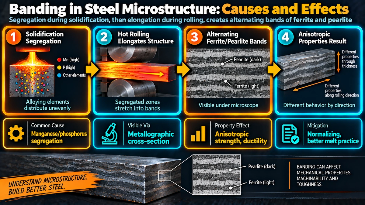
Banding is the alignment of two or more microstructural constituents into thin, roughly parallel bands or layers, oriented in the direction the steel was rolled. In plain carbon and low alloy steels, the most common form by far is ferrite-pearlite banding: alternating layers of soft, ductile proeutectoid ferrite and harder, stronger pearlite, typically 10 to 100 micrometres thick, running the length of the plate. Related banded patterns can also appear as martensite-bainite banding in quenched and tempered steels, or as banded inclusions such as manganese sulphide stringers.
Unlike random compositional noise, banding is a directional, planar feature. Viewed on a section cut parallel to the rolling plane, the bands appear as broad, roughly uniform layers. Viewed on a section cut perpendicular to the rolling direction (transverse to rolling), the same bands appear as thin, closely spaced stripes. This directionality is the reason banding produces anisotropic mechanical properties rather than simply lowering average properties uniformly.
How Banding Forms: From Cast Slab to Rolled Plate
Banding has its origin at the steelmaking stage, long before rolling or welding, and develops in two linked steps.
Step 1 — Manganese segregation during solidification of the cast slab
As liquid steel solidifies in the continuous caster, manganese partitions preferentially into the remaining liquid ahead of the growing dendrites, in the same manner described for weld metal solidification in the segregation guide, because manganese has a partition coefficient below 1 in iron. This produces manganese-rich interdendritic regions and manganese-lean dendrite cores at the scale of the as-cast structure, before any rolling has taken place.
Step 2 — Elongation during hot rolling
When the cast slab is subsequently reheated and hot rolled into plate or bar, the compositional bands inherited from solidification are mechanically stretched in the rolling direction along with the rest of the microstructure. A roughly equiaxed segregated region in the as-cast slab becomes a long, thin, ribbon-like band after the large reduction ratios typical of plate rolling. The degree of banding tends to increase with total rolling reduction, because greater reduction produces thinner, more closely spaced, and more sharply defined bands.
Step 3 — Preferential ferrite nucleation in manganese-lean bands
Manganese is an austenite stabiliser: it lowers the temperature at which austenite transforms to ferrite on cooling. During the final cooling of hot-rolled plate from the austenitising temperature, the manganese-lean bands (inherited from the dendrite cores) reach their transformation temperature first and nucleate proeutectoid ferrite preferentially. The manganese-rich bands remain austenitic to a lower temperature and are enriched in carbon rejected from the transforming ferrite, ultimately transforming to pearlite. The result is that the original solidification segregation pattern is chemically and microstructurally preserved as alternating ferrite and pearlite bands, clearly visible under the microscope.
Effects of Banding on Steel Properties
Anisotropic tensile and impact properties
Because banding is directional, mechanical tests give different results depending on the orientation of the test specimen relative to the bands. Charpy V-notch and tensile specimens taken with their length in the rolling direction (longitudinal) generally show the best toughness and ductility, since crack propagation must cut across the bands. Specimens taken transverse to rolling, and particularly through-thickness (short transverse) specimens, show measurably lower toughness and reduction of area, since cracks can propagate along the soft ferrite bands or any aligned inclusions with comparatively little resistance. This orientation dependence is why fabrication codes specifying through-thickness properties, such as for heavy-wall pressure vessel nozzles subject to lamellar tearing risk, require specific test orientations rather than accepting only longitudinal data.
Hydrogen induced cracking (HIC) susceptibility
In sour service piping and pressure vessels, hydrogen generated by corrosion reactions at the steel surface diffuses into the material and can recombine into molecular hydrogen at internal discontinuities. Banded regions, especially where banding coincides with centreline segregation and elongated manganese sulphide inclusions, are preferred sites for this recombination and the blistering and stepwise cracking that follows. Because of this link, sour service material specifications place tight limits on manganese and phosphorus content and require HIC testing per NACE TM0284 on plate intended for wet H2S service. See the related discussion of nickel restriction in sour service for how alloying additions interact with banding and HIC risk.
Weldability and HAZ behaviour
Banded base metal carries its compositional non-uniformity into the heat-affected zone during welding. Locally manganese-rich, carbon-enriched bands within the HAZ can transform to harder, more crack-susceptible microstructures than the bulk composition would predict, which is one reason carbon equivalent calculations based on ladle or check analysis provide only an average estimate of hydrogen cracking risk. See the carbon equivalent guide for the standard CE calculation and its limitations.
A Charpy impact test result that fails only in the transverse or through-thickness orientation, while passing comfortably in the longitudinal orientation on the same heat of plate, is a classic signature of banding. This pattern should prompt a metallographic check for banding severity before concluding that the material itself is out of specification.
Banding Compared with Weld Metal Segregation
Banding and weld metal segregation share the same root cause, solute partitioning during solidification, but they are not the same phenomenon and should not be confused when investigating a quality issue.
| Aspect | Banding (base metal) | Weld metal segregation |
|---|---|---|
| Where it forms | Cast slab or ingot, at the steel mill | Weld pool, during welding itself |
| Dominant element | Manganese (plus phosphorus) | S, P, Nb, Si, Mo depending on alloy |
| Mechanism that creates the pattern | Solidification segregation, then mechanical elongation by rolling | Dendritic solidification within a single weld pass or bead |
| Typical scale | 10 to 100 micrometre parallel bands, metres long | Micrometres (dendritic) to millimetres (pass-to-pass banding) |
| Primary consequence | Anisotropic toughness, HIC susceptibility | Hot cracking, reduced local corrosion resistance |
| Reference guide | This article | Segregation in weld metal |
Detection and Rating of Banding
| Method | What it shows |
|---|---|
| Macro-etch on a longitudinal section | Broad visual confirmation of banded appearance and centreline segregation |
| Optical microscopy, longitudinal plane | Ferrite-pearlite band thickness, spacing, and continuity |
| ASTM E1268 rating charts | Standardised severity index for comparing banding between heats and mills |
| Charpy impact testing, multiple orientations | Quantifies the practical toughness anisotropy caused by banding |
| Ultrasonic testing | Indirect detection through attenuation and backwall signal loss in severely banded or segregated plate |
Controlling and Reducing Banding
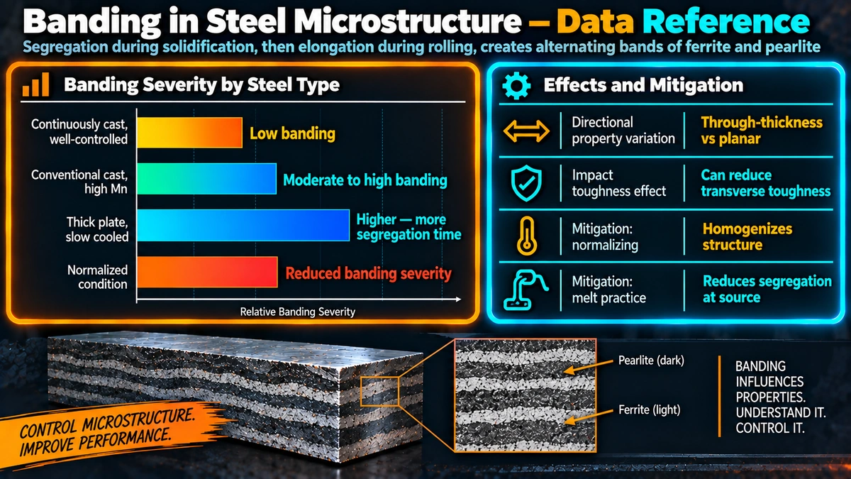
1. Continuous casting practice: soft reduction and electromagnetic stirring at the steelmaking stage reduce centreline segregation before it can be elongated by rolling.
2. Lower bulk manganese and phosphorus content, and calcium treatment to modify the morphology of manganese sulphide inclusions from elongated stringers to more benign globular particles.
3. Controlled rolling schedules that limit total reduction or introduce cross-rolling passes, reducing the degree of band elongation and improving transverse property uniformity.
4. Normalising heat treatment after rolling, which refines grain size and softens the visual contrast of banding, though it does not remove the underlying manganese segregation.
5. For critical, high-value components, a high-temperature homogenising anneal held long enough for substitutional Mn diffusion, which is the only treatment that meaningfully reduces the segregation itself rather than just its microstructural expression.
Plate specified for sour service, offshore structural use, or heavy-wall pressure vessel nozzles subject to through-thickness loading commonly includes explicit banding severity limits, minimum through-thickness reduction of area (Z-direction testing), and HIC test requirements, precisely because banding is otherwise invisible on a standard mill certificate that reports only bulk chemistry and longitudinal mechanical properties.
Practical Engineering Notes
When reviewing a material test report for critical service plate, remember that banding is a microstructural feature that a standard MTR chemistry and longitudinal tensile result cannot reveal. Where the application involves through-thickness loading, sour service, or lamellar tearing risk, request through-thickness reduction of area data, banding rating, or HIC test results specifically, rather than relying on bulk chemistry compliance alone.
Frequently Asked Questions
What is banding in steel microstructure?
Banding is the appearance of alternating, elongated layers of ferrite and pearlite (or other phase combinations) running parallel to the rolling direction in wrought steel plate, bar, and pipe. It forms when manganese and phosphorus segregated during solidification of the original cast slab or ingot are stretched into thin, parallel-oriented bands during hot rolling, and these compositional bands then control where ferrite and pearlite form on subsequent cooling.
How is banding different from segregation in weld metal?
Both originate from the same physical principle, elements partitioning between solid and liquid during solidification, but they occur in different products and stages. Weld metal segregation develops during solidification of the weld pool itself, at the scale of individual weld passes and dendrites, and is discussed in the guide to segregation in weld metal. Banding develops during solidification of the original steel slab or ingot at the mill, long before welding, and is then mechanically elongated by hot rolling into the parallel bands seen in base metal.
What causes ferrite-pearlite banding specifically?
Manganese is the primary driver. Manganese segregates into interdendritic regions of the cast slab during solidification, and because manganese is an austenite stabiliser, Mn-lean zones transform to ferrite first on cooling while Mn-rich zones remain austenitic longer and become enriched in carbon, ultimately transforming to pearlite. Hot rolling elongates these compositional zones into thin, parallel layers, and the final ferrite-pearlite pattern inherits this banded structure.
Why does banding matter for mechanical properties?
Banding produces anisotropic mechanical properties. Charpy impact and tensile tests taken through-thickness or transverse to the rolling direction typically show significantly lower toughness and ductility than tests taken in the rolling direction, because cracks propagate more easily along the soft ferrite bands and any aligned inclusions or centreline segregation.
Does banding increase hydrogen induced cracking risk?
Yes. In sour service applications, hydrogen generated by corrosion reactions diffuses into the steel and recombines into molecular hydrogen at internal defects and segregated bands, particularly centreline segregation associated with manganese sulphide inclusions and banded pearlite. This produces hydrogen induced cracking that propagates preferentially along the banded planes, which is why clean steel practice and banding control are core requirements of NACE MR0175/ISO 15156 material specifications.
How is banding severity measured and rated?
Banding is assessed on a polished and etched metallographic cross-section, typically viewed on a plane parallel to the rolling direction. ASTM E1268 provides standard reference charts and a rating index for classifying the severity of banded microstructures, allowing consistent comparison between heats and mills. Ultrasonic testing can also indirectly detect severe banding through its effect on sound attenuation and backwall signal quality.
Can banding be removed by heat treatment?
A full normalising treatment refines grain size and can reduce the visual contrast of banding somewhat, but it does not remove the underlying manganese segregation, so some degree of banding typically persists. A high-temperature homogenising anneal, held long enough for substitutional diffusion of manganese, is more effective but is rarely economical for standard plate and is mainly reserved for critical, high-value forgings and castings.
How is banding controlled at the steelmaking and rolling stage?
The most effective controls are applied before rolling begins: continuous casting practices that minimise centreline segregation (soft reduction, electromagnetic stirring), lower bulk manganese and phosphorus content, calcium treatment to modify manganese sulphide inclusion morphology, and controlled rolling schedules that reduce the degree of elongation of segregated zones. These measures are standard requirements in plate specifications for sour service and other critical through-thickness applications.
Recommended Reading
Steels: Microstructure and Properties
Core metallurgy reference covering phase transformations, banding, and processing-microstructure-property relationships in wrought steel products.
View on AmazonPrinciples of Solidification
Materials science reference on dendritic growth and partition coefficients underpinning segregation in cast slabs and ingots.
View on AmazonASM Handbook — Metallography and Microstructures
Comprehensive reference on metallographic technique, etching, and microstructure interpretation including banded and segregated structures.
View on AmazonWelding Metallurgy and Weldability
Graduate-level reference connecting base metal microstructure, including banding, to HAZ behaviour and weldability.
View on AmazonDisclosure: WeldFabWorld participates in the Amazon Associates programme (StoreID: neha0fe8-21). If you purchase through these links, we may earn a small commission at no extra cost to you. This helps support free technical content on this site.