Dilution in Welding: Causes and Control
Dilution in welding is usually introduced through weld overlay and cladding, where it directly determines whether a corrosion-resistant surface layer keeps its resistance to corrosion. But dilution is a fundamental feature of every fusion weld, not just overlay work — any time an arc melts base metal and mixes it with filler metal, the resulting weld deposit composition is somewhere between the two, and how far it sits toward one or the other depends on a set of controllable process variables.
This guide covers dilution as it applies to ordinary groove and fillet welds and dissimilar metal joints — what actually causes dilution to rise or fall, typical dilution ranges by welding process, and the practical joint design and parameter choices used to control it. For dilution calculation specific to weld overlay and cladding, and an interactive dilution calculator, see WeldFabWorld’s dedicated overlay dilution guide; this article focuses on the causes and control side of dilution across fusion welding generally.
What Dilution Actually Represents
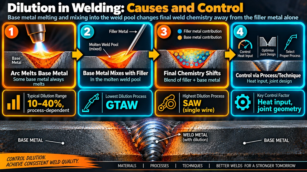
Dilution is the fraction of the finished weld bead that comes from melted base metal rather than deposited filler metal, expressed as a percentage of the total weld cross-sectional area. A weld with 20% dilution means the final weld metal composition is roughly 80% attributable to the filler and 20% to the melted base metal it mixed with, and because most base and filler metals differ in composition to some degree, dilution always shifts the actual deposited composition away from the filler’s nominal analysis, whether that shift matters or not depends on how different the two compositions are and how sensitive the application is to the result.
Causes of Dilution
Welding Current and Heat Input
Higher welding current increases arc energy density and penetration depth, melting a larger volume of base metal for a given amount of filler deposited, which raises dilution. This is the single most direct lever available to a welder or procedure, and it is also why dilution and productivity often pull in opposite directions — higher current generally means faster deposition and travel speed, but also more base metal melted per unit of filler.
Arc Voltage and Arc Length
A longer arc (higher voltage for a given current) tends to spread the arc energy over a wider area, producing a wider, shallower weld pool with somewhat lower penetration and dilution, while a shorter, more concentrated arc drives deeper penetration and higher dilution. This interacts with current rather than acting entirely independently, but voltage remains a distinct control variable in most processes.
Travel Speed
The relationship between travel speed and dilution is process- and parameter-dependent rather than a single universal rule, but as a general pattern, slower travel speed at a given current allows more time for the arc to penetrate into the base metal at any given point, tending to increase dilution, while faster travel speed reduces the heat delivered per unit length and can reduce it, provided sufficient fusion is still achieved.
Welding Process Selection
Different processes have inherently different energy density and penetration characteristics independent of parameter settings. Submerged arc welding concentrates a large amount of current into a confined arc beneath the flux blanket, producing characteristically deep penetration and high dilution. GTAW, by contrast, allows more independent control of heat input separate from filler deposition rate, generally producing lower dilution. Process selection is therefore often the first and most impactful dilution control decision, made before any parameter is even set.
Joint Design
Root gap, land (root face) dimension, and bevel angle all directly affect how much base metal must melt to achieve fusion. A narrow root gap or thick land forces the arc to melt more base metal to achieve full penetration, increasing dilution, while a wider, more open joint preparation reduces the base metal contribution needed for the same fusion result. This is a purely geometric effect, independent of the welding parameters used.
Torch/Electrode Angle and Weld Technique
A drag (backhand) torch angle typically directs more arc force into the leading edge of the weld pool, producing deeper, more concentrated penetration and higher dilution, while a push (forehand) angle tends to spread the arc energy ahead of the pool, producing a wider, shallower penetration profile. Stringer bead technique generally produces higher, more concentrated penetration at a given travel speed than a wide weave, which spreads heat over a broader area.
Number of Weld Layers
The first layer deposited directly onto unmelted base metal always experiences the highest dilution in a multi-layer weld, since it is the only layer in direct contact with base metal on one side. Subsequent layers are deposited onto previously solidified weld metal rather than base metal, so each additional layer’s composition is progressively less influenced by the original base metal, approaching the nominal filler composition as layer count increases.
Typical Dilution Ranges by Process
| Process | Typical Dilution Range | Notes |
|---|---|---|
| GTAW (with filler) | 10-25% | Independent heat/filler control allows the lowest dilution among common arc processes |
| GTAW (autogenous, no filler) | Effectively 100% | No filler contribution — entire weld is remelted base metal |
| SMAW | 10-30% | Varies with electrode size, current, and technique |
| GMAW (short circuit transfer) | 10-20% | Lower heat input transfer mode |
| GMAW (spray transfer) | 20-40% | Higher current, deeper penetration than short circuit |
| FCAW | 15-35% | Depends on gas-shielded vs self-shielded sub-process and parameters |
| SAW (single wire) | 30-60% | Highest typical dilution of common processes; reduced with strip/twin-wire technique |
Effect on Weld Metal Composition and Properties
In similar-metal welds where filler and base metal chemistry are already close, moderate dilution has little practical consequence, since the diluted weld metal composition remains close to both the filler and the base metal regardless of the exact mixing ratio. The consequences become significant specifically in two situations.
Dissimilar Metal and Overmatched Filler Applications
When base metal and filler composition differ substantially — most commonly austenitic stainless steel welded to carbon or low-alloy steel — dilution shifts the actual deposited weld metal composition toward the base metal, which can move the resulting microstructure into an undesirable region. Carbon and iron pickup from a carbon steel base metal, for example, can shift an austenitic stainless weld deposit toward the martensite region of the Schaeffler diagram, producing a hard, crack-susceptible microstructure rather than the intended tough austenite-ferrite structure. This is why over-alloyed filler metals are specifically selected and calculated for dissimilar joints — chosen so that even after the expected dilution, the resulting composition still lands in the desired final zone. See WeldFabWorld’s delta ferrite guide for the full Schaeffler diagram discussion.
Carbon and Hardenability Pickup
Beyond stainless-to-carbon-steel combinations, welding into or across a higher-carbon or higher-alloy base metal can raise the effective carbon or alloy content of the weld deposit through dilution alone, independent of the filler metal’s own analysis. This can affect hardenability, cracking susceptibility, and post-weld heat treatment requirements, and is a factor worth checking whenever base metal chemistry is not closely matched to the filler, even in joints that are not conventionally described as “dissimilar metal” welds.
Controlling Dilution: Practical Techniques
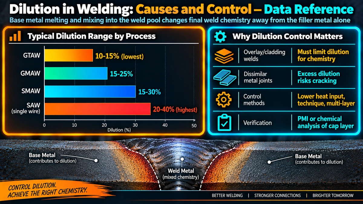
- Reduce welding current and overall heat input where joint strength and fusion requirements allow
- Use stringer bead technique rather than a wide weave to concentrate heat over a smaller area per pass
- Widen the joint root opening or reduce the land dimension so less base metal must melt to achieve fusion
- Use a push (forehand) torch angle rather than a drag angle where penetration profile allows it
- Deposit additional layers rather than relying on a single pass when the final composition must approach the nominal filler chemistry
- Increase travel speed where consistent with adequate fusion, reducing heat delivered per unit length
| Situation | Preferred Approach to Reduce Dilution |
|---|---|
| Overlay/cladding requiring specific corrosion resistance | Multi-layer deposition, strip or oscillated technique, lower current, see dedicated overlay dilution guide |
| Dissimilar metal groove weld | Over-alloyed filler selection calculated for expected dilution; buttering layers |
| General groove/fillet weld, similar metals | Dilution control usually unnecessary — focus on fusion and mechanical properties |
| High productivity requirement with dilution constraint | Process selection (e.g., GMAW spray vs SAW) balanced against required deposition rate |
Recommended Reference Books
Welding Metallurgy (2nd Ed.) — Sindo Kou
Covers weld pool mixing, dilution mechanics, and dissimilar metal weld metal composition prediction.
View on AmazonWelding Metallurgy: Principles — John Lippold
Detailed treatment of dissimilar metal welding, Schaeffler diagram application, and dilution-driven cracking mechanisms.
View on AmazonWelding Overlays and Claddings — Practical Reference
Focused reference on overlay materials, process selection, and dilution control for corrosion and wear-resistant overlay.
View on AmazonASM Handbook: Welding, Brazing, and Soldering
Comprehensive industry reference covering process-specific penetration and dilution characteristics.
View on AmazonDisclosure: WeldFabWorld participates in the Amazon Associates programme (StoreID: neha0fe8-21). If you purchase through these links, we may earn a small commission at no extra cost to you. This helps support free technical content on this site.
Frequently Asked Questions
What causes high dilution in a fusion weld?
Dilution rises with anything that increases arc penetration into the base metal: higher welding current and heat input, higher arc voltage, slower travel speed on some processes, and welding processes with inherently deep, concentrated penetration such as submerged arc welding. Joint design also matters directly, since a narrow root gap or thin land forces more base metal to melt and mix with the filler to achieve fusion, while a wider, more open joint preparation reduces the base metal contribution needed.
Which welding process typically has the highest dilution?
Submerged arc welding (SAW) typically produces the highest dilution of the common arc welding processes, often in the 30-60% range with a single wire, because of its high current density and deep penetration characteristics. GTAW with filler wire typically produces the lowest dilution among common arc processes, since the process allows more independent control of heat input and filler deposition, though autogenous GTAW without filler is, by definition, effectively all base metal.
Does dilution decrease with each subsequent weld pass?
Yes, generally. The first weld layer deposited directly onto the base metal experiences the highest dilution, since it is in direct contact with unmelted base material on one side. Subsequent layers are deposited onto previously solidified weld metal rather than base metal, so their composition is influenced much less by the original base metal and progressively approaches the nominal filler metal composition as more layers are added, which is why multi-layer weld overlay and buttering techniques are used when composition control is critical.
Why does dilution matter in dissimilar metal welding even outside overlay applications?
When joining two different base metals, or when either base metal composition differs significantly from the nominal filler metal chemistry, dilution shifts the actual as-deposited weld metal composition away from the filler’s nominal analysis in a way that can move the resulting microstructure into an undesirable region, such as shifting an austenitic stainless weld toward the martensite region of the Schaeffler diagram when diluted with carbon steel. This is why over-alloyed filler metals are frequently specified for dissimilar joints, calculated specifically to compensate for the expected dilution and still land in the desired final composition zone.
How can dilution be reduced without changing the welding process?
Within a given process, dilution can generally be reduced by lowering welding current and heat input, increasing travel speed, using a stringer bead technique rather than a wide weave, adjusting joint design to a wider root opening or land that requires less base metal melting to achieve fusion, and depositing additional layers rather than relying on a single pass to reach the required composition or properties. Torch or electrode angle also has an effect, since a drag angle typically produces deeper, more concentrated penetration than a push angle at the same parameters.
Can dilution ever be beneficial rather than a problem to minimize?
Yes. In some autogenous and similar-metal welds, dilution is simply how the joint achieves full fusion and is not a concern at all, since the base metal and filler compositions are intentionally matched. Dilution can also be used deliberately in certain buttering and transition-layer techniques, where a controlled, intermediate composition is the actual goal of that layer rather than an unwanted side effect, before subsequent layers with lower dilution build up the final desired composition.
Is dilution the same concern in overlay welding as in ordinary groove or fillet welds?
The underlying mechanism is identical, but the practical stakes differ. In overlay and cladding welds, dilution directly determines whether the deposited surface layer retains the corrosion or wear resistance it was selected for, since even moderate iron pickup from a carbon steel substrate can significantly degrade a corrosion-resistant alloy’s performance. In ordinary groove and fillet welds joining similar base metals, dilution is usually less critical since filler and base metal compositions are already close, though it remains an important consideration whenever dissimilar metals or significantly different alloy grades are joined.