MAWP Calculator: Maximum Allowable Working Pressure for Pressure Vessel Shells and Heads
Last updated:
A MAWP calculator gives the maximum allowable working pressure of a pressure vessel shell or head from its corroded thickness, inside radius, allowable stress and joint efficiency. The tool follows the ASME Section VIII Division 1 formulas, and the pressure vessel shell thickness calculator solves the same equations in the other direction. After using it, check your code knowledge with the ASME Section VIII Division 1 quiz.
Quick answer: A MAWP calculator finds the maximum allowable working pressure of a vessel part from its corroded thickness, inside radius, allowable stress and joint efficiency, using the ASME Section VIII Division 1 formulas. The vessel MAWP is the lowest value of any essential part, adjusted for static head. The standard hydrostatic test pressure is 1.3 times MAWP times the lowest stress ratio.
MAWP Calculator
Internal pressure, ASME Section VIII Division 1, thin-wall shells and heads. Example values are loaded; replace them with your data.
MAWP matters because it sets the pressure for the relief device, the hydrotest and the nameplate, and it is the number inspectors compare with operating pressure for the life of the vessel. This page gives the calculator first, then the formulas, a worked example and the code rules behind each input.
The tool covers internal pressure on thin-wall shells and heads. Nozzles, flanges and external pressure need separate checks, and the lowest result of all checks is the vessel MAWP.
Key takeaways
- MAWP is the gauge pressure limit at the top of a completed vessel, set by the weakest essential part and adjusted for static head.
- Shell and head formulas in ASME Section VIII Division 1 use the corroded inside radius and the corroded thickness.
- Hoop stress governs a cylinder, because the longitudinal formula gives about twice the pressure for the same thickness.
- The standard hydrostatic test pressure is 1.3 x MAWP x LSR at the top of the vessel.
- Joint efficiency, allowable stress at design temperature and corrosion allowance are the inputs that most often change the result.
What Is MAWP?
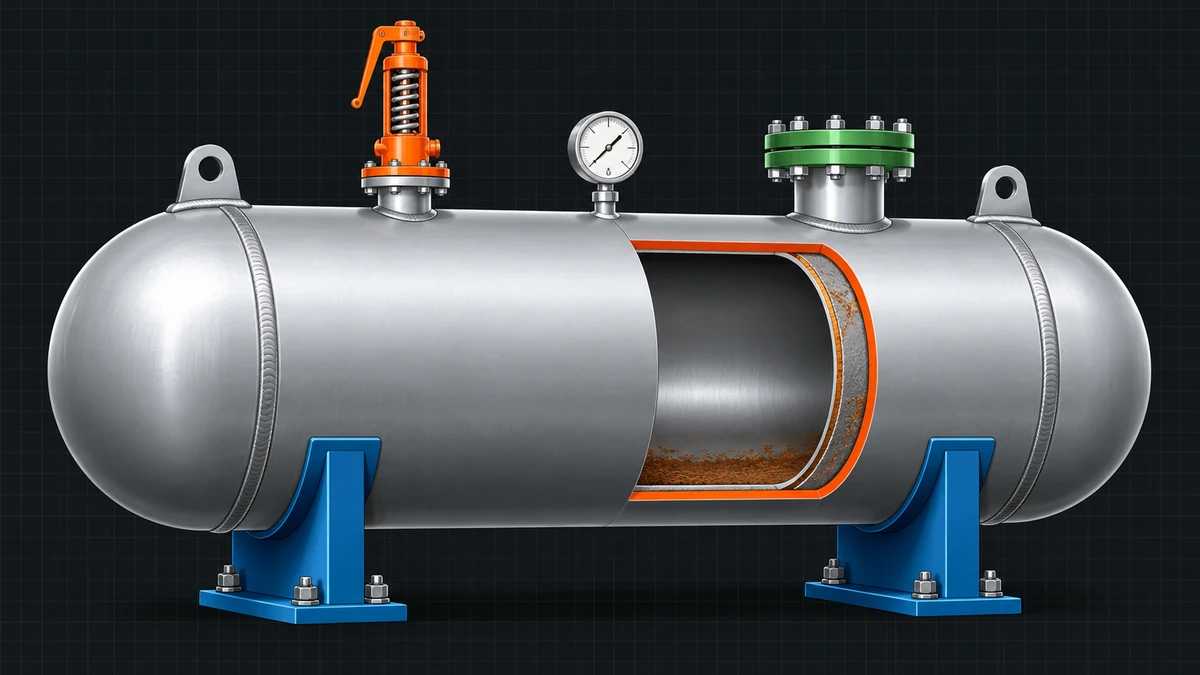
Maximum allowable working pressure (MAWP) is the gauge pressure limit that ASME Section VIII Division 1 permits at the top of a completed vessel at a stated coincident temperature.
ASME Boiler and Pressure Vessel Code (BPVC) Section VIII, Division 1, Rules for Construction of Pressure Vessels, defines MAWP as the least of the values calculated for the essential parts of the vessel. The value is adjusted for any difference in static head between the part and the top of the vessel. The rule appears in paragraph UG-98 of the Code. ASME publishes the Code, and this guide refers to the 2025 Edition.
MAWP is a calculated result, not a design input. It depends on the thickness actually built, the corrosion allowance, the material and the weld examination level. The table separates it from the pressures that people often confuse with it.
| Term | Meaning | Relation to MAWP |
|---|---|---|
| Design pressure | Pressure used with the design temperature to size the minimum required thickness | MAWP is equal to or higher |
| MAWP | Maximum gauge pressure at the top of the vessel, calculated from actual thickness | Basis for relief set pressure and test pressure |
| Operating pressure | Normal pressure in service | Kept below MAWP with a process margin |
| Relief set pressure | Pressure at which the relief device opens | Not more than MAWP (UG-134) |
| Hydrostatic test pressure | Water test pressure at the top of the vessel | 1.3 x MAWP x LSR (UG-99) |
Scope of the calculator. The tool above checks internal pressure on thin-wall shells and heads. Nozzles, flanges, supports and external pressure need separate checks. More tools of this kind are listed in the fabrication calculators collection on WeldFabWorld.
How Is MAWP Calculated for Shells and Heads?
MAWP is calculated by solving the ASME Section VIII Division 1 thickness equations for pressure, using the corroded inside radius and the corroded thickness. Cylindrical and spherical shells follow paragraph UG-27, and formed heads follow paragraph UG-32.
| Component | Thickness formula | MAWP formula | Valid when |
|---|---|---|---|
| Cylinder, circumferential stress | t = PR / (SE - 0.6P) | P = SEt / (R + 0.6t) | t not more than 0.5R, or P not more than 0.385SE |
| Cylinder, longitudinal stress | t = PR / (2SE + 0.4P) | P = 2SEt / (R - 0.4t) | t not more than 0.5R, or P not more than 1.25SE |
| Sphere or hemispherical head | t = PR / (2SE - 0.2P) | P = 2SEt / (R + 0.2t) | t not more than 0.356R, or P not more than 0.665SE |
| 2:1 ellipsoidal head | t = PD / (2SE - 0.2P) | P = 2SEt / (D + 0.2t) | Head depth equal to D/4 |
| Torispherical head, L/r = 16.67 | t = 0.885PL / (SE - 0.1P) | P = SEt / (0.885L + 0.1t) | t/L at least 0.002 |
The symbols are consistent across the formulas. P is the MAWP, S is the allowable stress at design temperature, E is the joint efficiency, t is the corroded thickness, R is the corroded inside radius, D is the corroded inside diameter and L is the corroded inside crown radius. All lengths and stresses must use consistent units, so mm with MPa or in with psi.
A cylinder has two checks because internal pressure loads it in two directions. Circumferential (hoop) stress acts across the longitudinal weld and normally governs. Longitudinal stress acts across the circumferential weld and allows about twice the pressure for the same thickness. The calculator takes the lower value for a governing check.
If you are sizing the plate rather than checking it, a shell thickness calculation solves the same equations for required thickness at a given pressure. For head steel quantities, the dish end weight calculator estimates the weight of a formed head.
How Do You Use the MAWP Calculator?
To use the MAWP calculator, select the component, enter the new dimensions with corrosion allowance, add the allowable stress and joint efficiency, and press Calculate. The tool returns the part MAWP, the MAWP at the top of the vessel and the hydrotest pressure with a full step-by-step breakdown.
- Choose units and component. Select metric or imperial units, then pick the cylindrical shell, sphere, 2:1 ellipsoidal head or torispherical head you want to check.
- Enter the new dimensions. Enter the inside diameter, nominal plate thickness, corrosion allowance and, if the shell is pipe, the thickness undertolerance of the material specification.
- Enter the allowable stress. Enter the allowable stress S for the material at the design temperature from ASME BPVC Section II, Part D.
- Enter the joint efficiency. Enter the joint efficiency E from the weld examination level, and the circumferential joint value if it differs from the longitudinal joint.
- Add static head and test factor. Enter the liquid height above the part, the specific gravity and the lowest stress ratio, or leave the defaults of zero head effect and 1.00.
- Calculate and read the result. Press Calculate MAWP or the Enter key. Read the part MAWP, the MAWP at the top of the vessel and the hydrotest pressure, and copy the step-by-step breakdown into your calculation sheet.
The tool converts values when you switch units, and each result is shown in MPa or psi together with bar and kPa. It does not store or transmit any of your data.
Worked Example: MAWP of a Cylindrical Shell and a 2:1 Head
The example calculates the MAWP of a carbon steel shell course and its 2:1 head, then finds the vessel MAWP and the hydrotest pressure. The inputs are assumed, so replace them with your own data and the allowable stress from your design temperature.
The bottom shell course governs because it carries the 6 m liquid column. Without static head the shell value of 1.968 MPa would be the limit, so the head of liquid costs about 3 percent of the margin in this case. Both numbers can be reproduced in the calculator by loading the default values.
What Inputs Control the MAWP Result?
Four inputs control the MAWP result: the allowable stress S, the joint efficiency E, the corroded thickness and the static head. Each one must be traceable to a code table, a drawing or a stated design basis.
Where does the allowable stress S come from?
The allowable stress S is the stress value for the material at the design temperature, taken from ASME BPVC Section II, Part D, Table 1A for ferrous materials. The values already include the Code’s design margins on tensile and yield strength, and they fall as temperature rises. Material grades are tied to tensile and yield data from tests such as those described in the guide to mechanical testing of welds and plate. Always use the value at the design temperature, not at room temperature.
How is joint efficiency E chosen?
Joint efficiency E reflects the weld examination level, and it comes from the joint types and examination categories in paragraph UW-12. For a double-welded butt joint (Type 1), E is 1.00 with full radiography, 0.85 with spot radiography and 0.70 with no radiography. A lower efficiency lowers MAWP in direct proportion.
The welding that creates the joint must also be qualified. Background on the joints themselves is in the guide to welding joint types, and the material and filler groupings used for qualification are explained in the P-Number, Group Number and F-Number guide.
How do corrosion allowance and undertolerance enter the calculation?
Corrosion allowance (CA) is extra metal thickness added to cover expected loss over the design life, and the calculation uses the corroded condition. The inside radius increases by CA and the thickness decreases by CA. If the shell is made from pipe, the manufacturing undertolerance of the pipe specification, commonly 12.5 percent for seamless pipe, also reduces the usable thickness. Selecting the right allowance starts with the damage mechanism, as covered in the guide to types of corrosion.
How is static head applied?
Static head is the pressure of the liquid column between the part and the top of the vessel. It equals fluid density times gravity times height, or about 9.81 kPa per metre (0.4335 psi per foot) for water. The calculator subtracts it from the part MAWP so that the result is stated at the top of the vessel, as the Code requires.
How Does MAWP Relate to Hydrotest Pressure and Design Temperature?
MAWP sets the pressure for the standard hydrostatic test and the upper limit for the relief device, and it is always stated with a coincident temperature. The hydrotest pressure is 1.3 times MAWP multiplied by the lowest stress ratio (LSR), measured at the top of the vessel.
How is the hydrotest pressure found?
Paragraph UG-99 gives the standard hydrostatic test pressure as 1.3 x MAWP x LSR. The LSR is the lowest ratio, among the pressure-boundary materials, of the allowable stress at test temperature to the allowable stress at design temperature. For carbon steel vessels that are tested near ambient temperature the ratio is usually 1.00 or higher. A pneumatic test under paragraph UG-100 uses 1.1 x MAWP x LSR and carries much higher stored-energy risk.
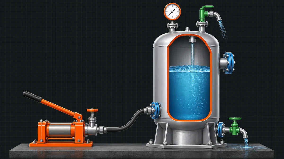
The test gauge should cover the test pressure comfortably. Paragraph UG-102 asks for a dial range of preferably about double the test pressure, and never less than 1.5 times or more than 4 times. Vent every high point before pressurising, and keep the vessel supports rated for the filled weight.
What is the link with minimum design metal temperature?
MAWP is paired with a coincident temperature, but a separate stamped value, the minimum design metal temperature (MDMT), governs low-temperature toughness. Whether impact testing is needed depends on the material, thickness and MDMT, as explained in the guide to UG-84 Charpy impact test requirements. A vessel can have an adequate MAWP and still need toughness testing.
How Is MAWP Used for Vessels Already in Service?
For vessels in service, inspectors recalculate MAWP with measured thickness and the corrosion expected before the next inspection, then compare the result with the operating and relief set pressures. The rules for in-service inspection, rating, repair and alteration sit in API 510, Pressure Vessel Inspection Code, published by the American Petroleum Institute (API).
A lower recalculated MAWP does not automatically end service. Options include reducing the operating pressure, repairing the metal loss, or re-rating the vessel under the code of construction and the owner’s engineering approval. Certified inspectors carry out this work, and the path to that credential is described in the API 510 pressure vessel inspector certification guide.
Quick Reference: MAWP Formulas, Limits and Test Factors
The reference table collects the factors and checks used in the calculator. Print it with the design calculation, and confirm every value against the Code edition that applies to your vessel.
| Item | Value or rule |
|---|---|
| Dimensions used | Corroded: R = D/2 + CA, t = tn – CA |
| Joint efficiency, Type 1 butt joint | 1.00 full RT, 0.85 spot RT, 0.70 no RT |
| Cylinder, hoop stress | P = SEt / (R + 0.6t) |
| Cylinder, longitudinal stress | P = 2SEt / (R – 0.4t) |
| Sphere and hemispherical head | P = 2SEt / (R + 0.2t) |
| 2:1 ellipsoidal head | P = 2SEt / (D + 0.2t) |
| Torispherical head (L/r = 16.67) | P = SEt / (0.885L + 0.1t) |
| Static head, water | 9.81 kPa per metre, or 0.4335 psi per foot |
| Vessel MAWP | Lowest part value, adjusted for static head |
| Hydrotest pressure | 1.3 x MAWP x LSR at the top of the vessel |
| Pneumatic test pressure | 1.1 x MAWP x LSR |
| Relief set pressure | Not more than MAWP |
Rule of thumb. Calculate in the corroded condition, let the hoop stress govern cylinders, take the lowest part value for the vessel, and subtract static head before stating MAWP at the top.
What Are the Common Mistakes and Limitations?
Most MAWP errors come from using the wrong dimensions or the wrong stress value, not from the formulas. These are the mistakes that reviewers and inspectors correct most often.
- Using nominal thickness and new inside radius when the calculation basis is the corroded condition.
- Taking the allowable stress at room temperature instead of at the design temperature.
- Using a joint efficiency of 1.00 without the radiography that justifies it.
- Forgetting static head, which lowers the MAWP of lower courses.
- Applying thin-wall formulas to thick shells outside the stated limits.
- Treating the shell result as the vessel MAWP when a flange, nozzle or reinforcement pad is weaker.
- Mixing units, such as thickness in inches with stress in MPa.
- Using the head formula for a head with a different depth ratio or knuckle radius.
What does the calculator not cover?
The calculator checks internal pressure on shells and heads using the thin-wall formulas only. It does not cover external pressure, nozzle reinforcement, flange ratings, supports, wind and seismic loads, cyclic service or non-ferrous material rules. Flange ratings come from ASME B16.5, Pipe Flanges and Flanged Fittings, and the lowest result of all checks becomes the vessel MAWP.
Edition and specification. Requirements depend on the code edition and contract specification applicable to your project. This tool supports hand checks and learning, and it does not replace a design calculation prepared and certified by a qualified engineer.
Frequently Asked Questions
What is MAWP and how is it different from design pressure?
Maximum allowable working pressure (MAWP) is the maximum gauge pressure permitted at the top of a completed vessel at its coincident temperature, calculated from the actual thickness of the weakest essential part. Design pressure is the value used to size the minimum required thickness. MAWP is equal to or higher than design pressure, because plate is bought in standard thicknesses and the built vessel is usually stronger than the minimum design.
How do you calculate MAWP for a cylindrical shell?
Use the ASME Section VIII Division 1 thin-wall formulas solved for pressure. For circumferential stress, P = S E t / (R + 0.6 t), and for longitudinal stress, P = 2 S E t / (R – 0.4 t). Use the corroded inside radius and the corroded thickness, then take the lower of the two values. The circumferential result almost always governs for a cylinder.
Does corrosion allowance reduce MAWP?
Calculations are normally made in the corroded condition, so the inside radius grows by the corrosion allowance and the thickness shrinks by the same amount. The MAWP printed on the nameplate therefore already assumes the metal loss has occurred. A new vessel has a margin above that value until the corrosion happens. See the guide to corrosion and its types for how loss mechanisms are chosen.
What is the hydrotest pressure for a given MAWP?
The standard hydrostatic test pressure in ASME Section VIII Division 1 is 1.3 times the MAWP multiplied by the lowest stress ratio (LSR), measured at the top of the vessel. The LSR is the lowest ratio of the allowable stress at test temperature to the allowable stress at design temperature for the pressure-boundary materials. For many carbon steel vessels at moderate temperature the LSR is 1.0. The calculator above shows this value alongside the MAWP.
Why is the MAWP at the bottom of a vessel lower than at the top?
MAWP is defined at the top of the vessel in its normal operating position. A part lower in the vessel carries the liquid column in addition to the gas pressure, so its available pressure margin is reduced by the static head. The Code therefore adjusts each part’s MAWP for the difference in static head between that part and the top. The calculator subtracts this head when you enter the liquid height and specific gravity.
Can MAWP be higher than the design pressure?
Yes. MAWP is calculated from the thickness actually supplied, which is normally greater than the minimum required thickness. Plate thickness steps, corrosion allowance and formed head thinning all push the real value above the design pressure. The nameplate may show the MAWP or the design pressure depending on the owner’s specification, so check the data report. Use the pressure vessel shell thickness calculator to size the minimum thickness first.
Which part usually limits the MAWP of a vessel?
The vessel MAWP is the lowest value of any essential part, so the limit can be a shell course, a head, a nozzle neck, a reinforcement pad, a flange or a bolted cover. This calculator checks only shells and heads under internal pressure. Flange ratings from ASME B16.5 and nozzle reinforcement checks must be carried out separately, and the lowest of all results becomes the vessel MAWP.
Key Terms
- Maximum allowable working pressure (MAWP)
- The maximum gauge pressure permitted at the top of a completed vessel at its coincident temperature.
- Design pressure
- The pressure used with the design temperature to determine the minimum required thickness.
- Allowable stress (S)
- The maximum stress value for a material at a given temperature, taken from ASME Section II, Part D.
- Joint efficiency (E)
- A factor that reduces allowable stress at a welded joint according to the weld type and examination level.
- Corrosion allowance (CA)
- Extra metal thickness provided to cover expected metal loss during the design life.
- Lowest stress ratio (LSR)
- The lowest ratio of allowable stress at test temperature to allowable stress at design temperature among the pressure-boundary materials.
- Static head
- The pressure produced by the weight of a liquid column above a given point in the vessel.
Conclusion
A MAWP calculator turns shell and head geometry into a pressure limit by solving the ASME Section VIII Division 1 equations in the corroded condition. The vessel MAWP is the lowest value of all essential parts, stated at the top of the vessel after subtracting static head, and the standard hydrotest pressure follows as 1.3 times MAWP times the lowest stress ratio. Shell and head checks are only part of the job, because flanges, nozzles and reinforcement can set a lower limit.
As a next step, review how welds that carry these pressures are qualified with the ASME Section IX quiz, which covers the procedure and welder rules behind every joint efficiency used in the calculation. Then run your own data through the calculator above and keep the step-by-step breakdown with your calculation sheet.
About This Guide
This guide was prepared by the WeldFabWorld technical team from the standards listed in the references below. Verify every requirement against the code edition and specification applicable to your project, and have a qualified engineer approve any design calculation.
Standards and References
- ASME Boiler and Pressure Vessel Code, Section VIII, Division 1, Rules for Construction of Pressure Vessels (paragraphs UG-27, UG-32, UG-98, UG-99, UG-100, UG-102, UG-134, UW-12 and UG-84), American Society of Mechanical Engineers (asme.org).
- ASME Boiler and Pressure Vessel Code, Section II, Part D, Properties (Metric and Customary), American Society of Mechanical Engineers.
- ASME Boiler and Pressure Vessel Code, Section IX, Welding, Brazing, and Fusing Qualifications, American Society of Mechanical Engineers.
- ASME B16.5, Pipe Flanges and Flanged Fittings: NPS 1/2 Through NPS 24 Metric/Inch Standard, American Society of Mechanical Engineers.
- API 510, Pressure Vessel Inspection Code: In-service Inspection, Rating, Repair, and Alteration, American Petroleum Institute (api.org).