Pipe Thermal Expansion Calculator
Pipe thermal expansion equals the expansion coefficient times length times temperature change. A 50 m carbon steel run heated by 180°C grows about 105 mm. Enter your values below. This tool covers service expansion; for welding shrinkage read the thermal expansion and contraction weld distortion guide, and find sister tools in the Fabrication & Calculators category.
Calculate Pipe Thermal Expansion
- Free expansion depends on material, length and temperature change only. Diameter and wall thickness do not matter.
- Stainless steel grows about 35 to 50 percent more than carbon steel for the same length and temperature change.
- Fully restrained pipe develops stress equal to modulus times coefficient times temperature change, regardless of length.
- Real piping absorbs movement through bends, loops, expansion joints, guides and anchors, checked by flexibility analysis.
- Use mean coefficients for screening and the code expansion tables for design.
What Is a Pipe Thermal Expansion Calculator?
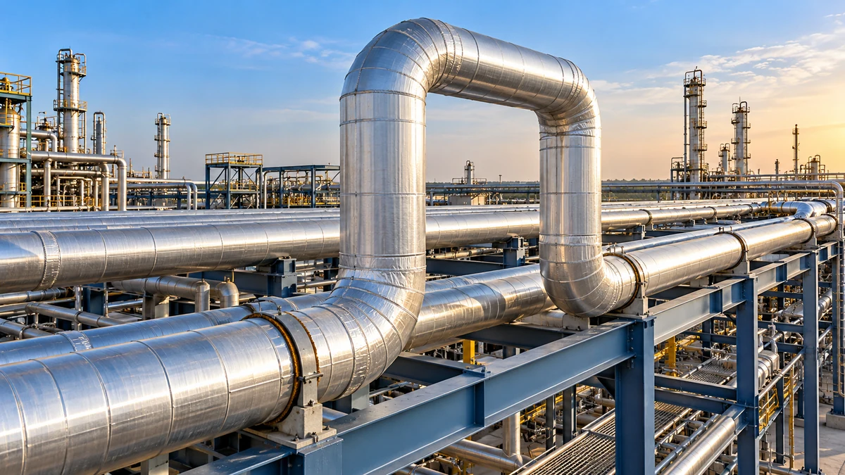
A pipe thermal expansion calculator is a tool that estimates pipe length change from material, length and temperature change.
Steel gets longer when it is heated and shorter when it is cooled. The change looks small on a short spool, but on a 100 m steam line it reaches a couple of hundred millimetres. If nothing is built in to take that movement, the pipe pushes on nozzles, supports and equipment, and the stress can damage them. A calculator turns the first question, how much will it move, into a number in seconds.
The result also feeds the next decisions: where to place anchors and guides, how large a loop is needed and whether an expansion joint is justified. Pipe size and class come from separate checks, such as the pipe wall thickness calculator for B31.3 and B31.1. Thermal movement sits beside them, not inside them.
How much does a steel pipe expand?
Carbon steel pipe expands roughly 1.2 mm per metre for every 100°C rise, and austenitic stainless steel roughly 1.7 mm per metre. The change in length equals the mean expansion coefficient multiplied by the original length and the temperature change, and it does not depend on pipe diameter or wall thickness.
How Do You Calculate Pipe Thermal Expansion?
The method is the same for any metal pipe. Follow the six steps below, which match the calculator and the HowTo markup on this page.
- Set the straight pipe length between anchors, or between a fixed point and the free end.
- Find the temperature change: operating temperature minus installation temperature. A negative result means contraction.
- Select the mean coefficient of thermal expansion for the material over that range.
- Multiply coefficient by length by temperature change to get the change in length.
- If the pipe is fully restrained, multiply modulus of elasticity by the coefficient by the temperature change to get stress.
- Compare the movement with the flexibility available, and add loops, bends or expansion joints with guides where it does not fit.
Worked Example: 50 m Carbon Steel Line
The numbers are illustrative values chosen to show the method. The pipe size is NPS 8 schedule 40, with an outside diameter of 219.1 mm and a wall of 8.18 mm. Click Load Worked Example to reproduce the result.
The free growth of about 105 mm must go somewhere. The restrained stress is far above the yield strength of ordinary carbon steel pipe, which tells you the line cannot simply be anchored at both ends. Something has to flex, slide or bend, and that is why every long hot line needs a flexibility plan.
The restrained stress shown by the calculator is a theoretical upper bound for a fully fixed straight pipe. Real systems are flexible, and the stress they carry from expansion is evaluated by flexibility analysis against the allowable displacement stress range of the governing code.
Which Expansion Coefficient Should You Use?
Use the mean coefficient of the actual alloy over your temperature range. The table lists the typical values built into the calculator. They suit screening. For design, take total expansion from the code or from the material supplier at the design temperature.
| Material | α (x10-6 per °C) | E (GPa) | Note |
|---|---|---|---|
| Carbon and low alloy steel | 11.7 | 200 | Baseline |
| Austenitic stainless 304 | 17.2 | 193 | High |
| Austenitic stainless 316 | 16.0 | 193 | High |
| Duplex stainless | 13.0 | 200 | Near steel |
| Nickel alloy 625 | 12.8 | 205 | Near steel |
| Copper | 16.5 | 117 | Soft, low E |
| Aluminium | 23.1 | 69 | Highest |
The figure below applies those coefficients to a common case: 100 m of pipe heated by 100°C. Austenitic stainless steel grows far more than carbon steel, which is why dissimilar joints and mixed-material racks need care. The properties and weld behaviour of duplex grades are described in the duplex stainless steel guide.
Coefficients rise with temperature. A single mean value understates growth over a wide range for steel, and the error grows with the span. The code tabulates total thermal expansion from a reference temperature for the standard materials. Use those tables, edition checked, whenever the number goes into a stress report.
What Happens When a Pipe Cannot Expand?
When a pipe is held fixed at both ends, the movement cannot happen, so the metal is compressed instead. The compressive stress equals modulus times coefficient times temperature change. It does not depend on length, which surprises many people: a 5 m restrained spool and a 500 m restrained line carry the same stress for the same temperature change. Length only decides how far the pipe would have moved.
The force on the restraints is the stress times the metal cross-section. For heavy pipe it runs into hundreds of kilonewtons, enough to buckle a line, overload a nozzle or move a support. Pressure adds its own load to the picture, which the burst pressure calculator addresses separately from thermal effects.
| Item | Free to expand | Fully restrained |
|---|---|---|
| Result | Length change ΔL | Thermal stress and anchor force |
| Depends on length | Yes | No |
| Depends on wall and diameter | No | Force only |
| Main risk | Collision, loss of support, equipment displacement | Buckling, yielding, overloaded nozzles |
| Typical remedy | Allow room and guides | Add flexibility or an expansion joint |
Thermal movement also loads welds in service, and cycling heat-up and cool-down can fatigue them. If you need background on stress left in welds by the fabrication itself, the guide to residual stress in welded joints covers formation and impact on fatigue life.
How Do Piping Systems Absorb Thermal Expansion?
Designers rarely fight expansion. They give the pipe a path to flex. The usual tools are changes of direction, loops, expansion joints and a set of guides and anchors that control where movement happens.
- Natural flexibility. L-bends and Z-bends use the pipe itself as a spring. Fittings such as long radius elbows lengthen the flexible path, and the elbow weight calculator helps with the resulting take-off.
- Expansion loops. A U-shaped loop adds a long flexible leg for long straight runs on racks.
- Expansion joints. Bellows joints absorb movement in a short space, but they create pressure thrust that anchors must carry, and they need guides to stay aligned.
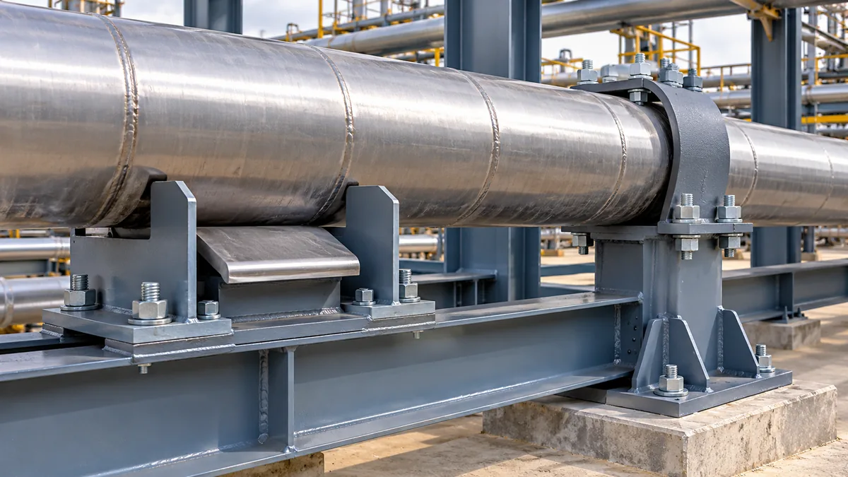
- Guides and anchors. Anchors fix a point. Guides allow axial movement and prevent sideways motion. Sliding supports carry weight without resisting expansion.
Weld type matters at anchors and branch connections, because stress concentrates at joints. The comparison in butt weld versus socket weld fittings shows why many cyclic lines use butt welds. The flexibility rules and allowable stress ranges belong to the governing code, and the full process piping rules are described in the ASME B31.3 process piping guide. If your project falls under power piping, compare the two in ASME B31.1 versus B31.3.
Flanged joints are temperature sensitive too, since pressure rating drops as temperature rises. Check class and temperature with the ASME B16.5 flange pressure and temperature rating calculator.
How Is Service Expansion Different from Weld Distortion?
Both involve heat and metal movement, but they are separate problems with separate controls. Service expansion is elastic, reversible and driven by operating temperature. Weld distortion is permanent and driven by localised heating and cooling during welding. This page covers the first. The full treatment of the second sits in the thermal expansion, contraction and weld distortion guide for inspectors.
| Feature | Service expansion | Weld distortion |
|---|---|---|
| Cause | Operating temperature change of the whole pipe | Local heating and cooling at the weld |
| Nature | Elastic, reversible | Permanent |
| Tool | Expansion formula and flexibility analysis | Joint design, sequencing and fixturing |
| Controlled by | Loops, guides, joints, supports | Weld procedure and fabrication practice |
How Accurate Is a Pipe Expansion Calculation?
For a straight free pipe with a known temperature and a correct coefficient, the formula is accurate to within a few percent. The main error sources are the temperature assumed, because the metal may not match the fluid temperature, and the coefficient, which changes with temperature. Insulation, tracing, solar heating and wall-to-fluid temperature gaps all move the metal temperature.
- Use the highest and lowest metal temperatures, not only the process value.
- For contraction, use the lowest expected ambient or cold service temperature.
- For long spans in sun and shade, check both extremes.
- For mixed materials, calculate each section with its own coefficient.
Expansion at the pipe is only part of the story. A hot line can also move its connected equipment, so check nozzle movement on vessels and exchangers. Use code expansion data for any figure that appears in a stress report, and verify the edition against your project specification.
What Are the Common Mistakes?
- Using the wrong temperature difference. Use the metal temperature at installation, not 20°C by habit.
- Mixing °C and °F. A difference of 100°F is 55.6°C, not 100°C.
- Thinking diameter changes free growth. It does not. Only force depends on cross-section.
- Treating restrained stress as a design stress. It is an upper bound for a fixed straight pipe, not a code check.
- Using carbon steel values for stainless pipe. The error is 35 to 50 percent.
- Forgetting contraction. Cold service and shutdown can pull pipe off supports or load welds in tension.
- Ignoring lateral movement. Movement at a bend is not straight along the run.
Quick Reference: Pipe Expansion Cheat Sheet
| Item | Value |
|---|---|
| Length change | ΔL = α x L x ΔT |
| Restrained stress | σ = E x α x ΔT |
| Anchor force | F = σ x metal area |
| Carbon steel rule | About 1.2 mm per metre per 100°C |
| Stainless 304 rule | About 1.7 mm per metre per 100°C |
| Aluminium rule | About 2.3 mm per metre per 100°C |
| Temperature difference | °F difference x 5/9 = °C difference |
| Length and stress units | 1 in = 25.4 mm; 1 MPa = 0.145038 ksi; 1 N = 0.224809 lbf |
Key Terms
- Coefficient of thermal expansion
- The fractional length change per degree of temperature change for a material.
- Elastic modulus
- The ratio of stress to strain in the elastic range, in GPa or MPa.
- Anchor
- A support that fixes the pipe against movement in all directions.
- Guide
- A support that allows movement along the pipe axis and prevents sideways motion.
- Expansion loop
- A bend or U-shaped section that gives a straight line extra flexibility.
- Expansion joint
- A flexible element, often a bellows, that absorbs axial or lateral movement.
- Displacement stress range
- The stress caused by pipe movement that is compared with the code allowable.
Standards and References
- ASME B31.3, Process Piping, issued by ASME. Flexibility rules and thermal expansion data are in this standard.
- ASME B31.1, Power Piping, issued by ASME.
- ASME B36.10M, Welded and Seamless Wrought Steel Pipe, issued by ASME. Source of the pipe size convention used in the example.
Verify the edition and the tabulated expansion values against the standard named in your project specification. This page does not reproduce copyrighted tables.
Frequently Asked Questions
How do you calculate pipe thermal expansion?
Multiply the mean coefficient of thermal expansion by the pipe length and by the temperature change. For carbon steel at 11.7 x 10^-6 per degree C, a 50 m pipe heated by 180 degrees C grows about 105 mm. Diameter and wall thickness do not affect free expansion.
Does pipe diameter or wall thickness affect thermal expansion?
No. Free thermal expansion depends only on material, length and temperature change. Diameter and wall thickness matter for the force a restrained pipe exerts, because force equals stress times metal cross-section.
How much does steel pipe expand per metre?
Carbon steel pipe grows about 1.2 mm per metre for every 100 degrees C of temperature rise. Austenitic stainless steel grows about 1.6 to 1.7 mm per metre, and aluminium about 2.3 mm per metre for the same rise.
Why is restrained thermal stress independent of pipe length?
A fully fixed pipe is compressed by the strain it would have had, which is the coefficient times the temperature change. Stress is modulus times that strain. Length cancels out, so a short and a long restrained pipe carry the same stress.
How do piping systems absorb thermal expansion?
Designers use natural flexibility from bends, expansion loops, bellows expansion joints and a scheme of anchors, guides and sliding supports. A flexibility analysis checks the displacement stress against the allowable range of the governing code.
Is pipe thermal expansion the same as weld distortion?
No. Service expansion is elastic and reversible, driven by operating temperature. Weld distortion is permanent and driven by local heating and cooling during welding. They need different controls.
Can this calculator handle contraction?
Yes. Enter an operating temperature lower than the installation temperature. The change in length shows as contraction, and the restrained stress is tensile.
Conclusion
Pipe thermal expansion is a simple product: coefficient times length times temperature change. The result is independent of pipe diameter and wall, but a restrained pipe converts that movement into stress and force, which is why long hot lines need loops, bends, joints and guides. Use the calculator to screen movement, pick the right material coefficient, and check the code tables before issuing a stress report. For your next step, confirm the pipe size with the Pipe Wall Thickness Calculator and add the line mass using the pipe weight calculator.