ASME B16.9 Fittings: Butt-Weld Dimensions, Ratings and Marking Explained
ASME B16.9 fittings are the factory-made wrought butt-weld fittings, such as elbows, tees, reducers and caps, that form most of the pipe joints in process and power piping. The standard fixes their overall dimensions, tolerances, marking and design-proof rules so that a fitting from one manufacturer lines up with a pipe or flange from another. It sits beside the flange standards covered in our guide to flange types, faces and grades, and it is one of the two fitting families compared in our butt weld vs socket weld fittings comparison.
ASME B16.9 fittings are factory-made wrought butt-weld fittings, such as elbows, tees, reducers, caps and stub ends, made to the ASME B16.9 standard in sizes NPS 1/2 through NPS 48. The standard fixes their overall dimensions, tolerances, marking and design-proof requirements, while the pressure rating follows the matching seamless pipe wall thickness and material.
This guide covers what B16.9 includes and excludes, the fitting types and their dimension symbols, how pressure ratings work, materials and marking, bevels and tolerances, design proof tests, and a practical receiving-inspection procedure. It is written for piping engineers, welding engineers, QA/QC and CWI inspectors, and fabrication planners. More standards guides are in the ASME Codes & Standards library.
The current edition is ASME B16.9-2024, issued in October 2024 as a revision of the 2018 edition. Clause and table references below were checked against the 2018 text, so confirm them against the 2024 edition and your project specification before you rely on them.
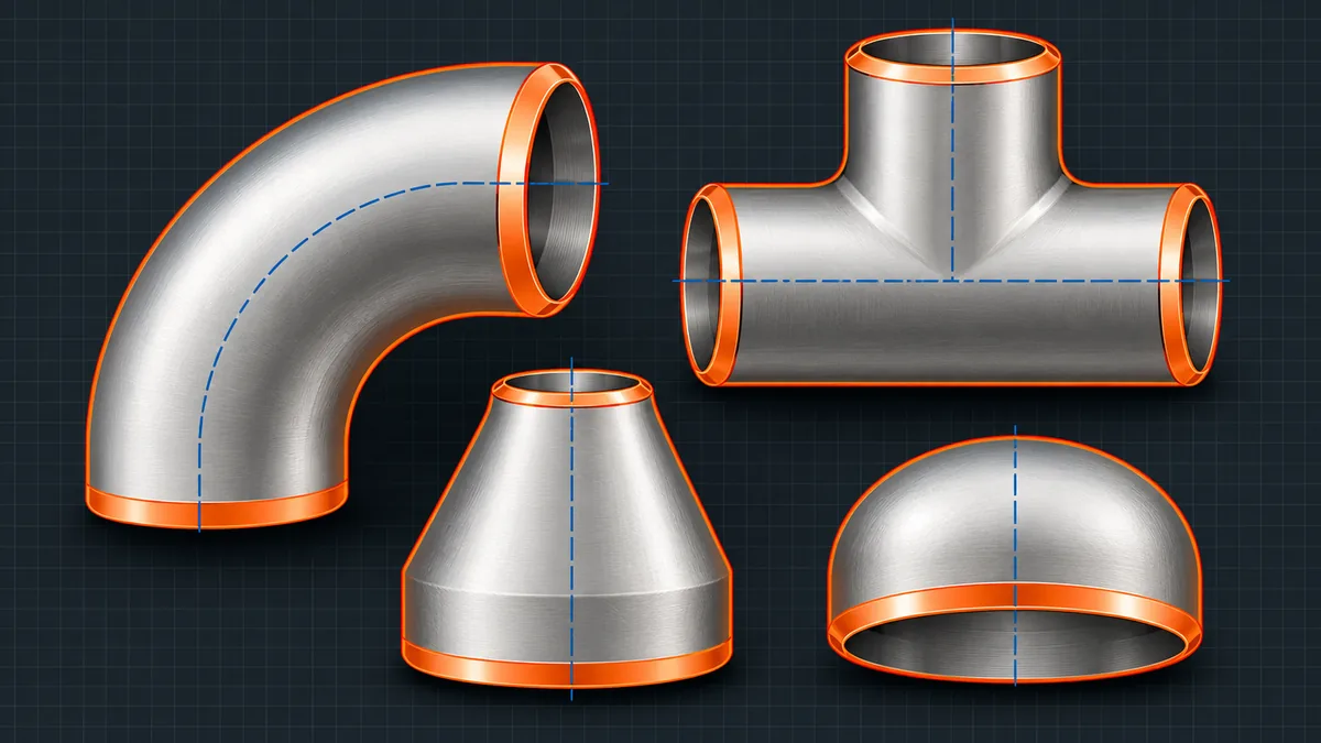
- ASME B16.9 covers factory-made wrought butt-weld fittings from NPS 1/2 through NPS 48 (DN 15 through DN 1200).
- Fittings are not assigned a pressure Class. Their rating is that of seamless pipe of equivalent material and the wall thickness shown in the marking.
- For NPS 1 and larger, a long radius 90-degree elbow has a center-to-end dimension A of 1.5 x NPS in inches; an NPS 6 elbow measures 229 mm.
- The prefix WP in the material grade marking, for example WPB, certifies that the fitting meets the standard dimensions.
- The standard does not require a production hydrostatic test of each fitting, but every fitting must be capable of passing the test the piping code requires for matching pipe.
- Fabricated laterals, field-cut segmented elbows and service selection are outside the standard.
What Is ASME B16.9?
ASME B16.9 is the dimensional standard for factory-made wrought butt-weld fittings, covering overall dimensions, tolerances, ratings, testing and markings for sizes NPS 1/2 through NPS 48. It is published by the American Society of Mechanical Engineers (ASME), and the current edition, B16.9-2024, supersedes the 2018 edition.
Standardization of welding fittings began in 1937, and the first edition appeared as ASA B16.9-1940. The size range reached NPS 48 in 1971, short radius elbows and returns were added in 2001, and 3D radius elbows and segmental elbow rules followed in 2006.
B16.9 is a product standard, not a piping design code. The piping code decides whether a fitting may be used in a given service, and B16.9 states that selection of fitting types and materials for a particular fluid service, and installation welding, are outside its scope.
What Does ASME B16.9 Cover and Not Cover?
B16.9 covers wrought fittings made from pipe, tubing, plate or forgings in the NPS 1/2 to NPS 48 range. Fittings may also be made to special dimensions, sizes, shapes and tolerances by agreement between the manufacturer and the purchaser.
- Included: long radius, short radius and 3D radius elbows, reducing elbows, 180-degree returns, straight and reducing tees and crosses, reducers, caps and lap joint stub ends.
- Excluded: fabricated laterals and other fittings made with circumferential or intersection welds, which are treated as pipe fabrication. Fabricated lap joint stub ends are the exception when they meet the ASTM material specification.
- Excluded: a field-segmented elbow. Once it is cut, it is no longer a B16.9 product, even if it started as one.
- Different standards: light-wall corrosion-resistant fittings (MSS SP-43) and high-test fittings (MSS SP-75) are published by the Manufacturers Standardization Society (MSS).
| Topic | Decided by B16.9? | Where the answer sits |
|---|---|---|
| Overall dimensions and tolerances | Yes | Tables 6.1-1 to 6.1-11 and Table 11-1 |
| Weld end bevel and wall transition | Yes | Section 8, Table 8-1 and Figure 8-1 |
| Marking and compliance prefix | Yes | Section 4 |
| Pressure rating basis | Yes, as matching seamless pipe | Section 2 and the applicable ASME B31 section |
| Material choice for the service | No | Piping code and owner specification |
| Installation welding | No | Welding procedure, Section IX and piping code |
| Hydrostatic test of each fitting | No, not required | Section 10; piping code for the finished system |
Which Fitting Types Does ASME B16.9 Include?
Each fitting type has a dimension symbol that fixes where the weld ends sit relative to the centerline or the overall length. Elbows and tees use center-to-end dimensions (A, B, C, M), returns use center-to-center O and back-to-face K, reducers use end-to-end H, and caps use length E.
| Fitting | Symbol | NPS 6 value | Relation |
|---|---|---|---|
| 90-degree long radius elbow | A | 229 mm (9.00 in) | 1.5 x NPS for NPS 1 and larger |
| 45-degree long radius elbow | B | 95 mm (3.75 in) | Tabulated by size |
| 90-degree short radius elbow | A | 152 mm (6.00 in) | 1.0 x NPS, NPS 1 to 24 |
| 90-degree 3D radius elbow | A | 457 mm (18.00 in) | 3.0 x NPS |
| 180-degree long radius return | O / K | 457 mm / 313 mm | O = 2 x A |
| Straight tee | C and M | 143 mm (5.62 in) each | Tabulated by size |
| Reducer, NPS 6 x 4 | H | 140 mm (5.50 in) | Tabulated by size pair |
| Cap | E / E1 | 89 mm / 102 mm | E for walls up to 10.92 mm, E1 for thicker walls |
| Lap joint stub end | F | 203 mm long, 89 mm short | Purchaser specifies the pattern |
How Do Long Radius, Short Radius and 3D Elbows Differ?
The three elbow families differ in bend radius. A long radius elbow has a radius of 1.5 times NPS, a short radius elbow uses 1.0 times NPS and a 3D radius elbow uses 3.0 times NPS. Long radius is the common default, short radius suits tight layouts but increases flow resistance, and 3D radius gives gentler bends for erosive or high-velocity service.
Because the radius controls how fast the flow direction changes, bends are often the first place where wall loss appears. Our guide to erosion-corrosion in piping systems explains why bends and reducers are inspected first.
Reducers are made concentric or eccentric, and either may have a conical or bell-shaped body. The standard does not prohibit a conical shape even where the drawing shows a bell. Straight conical and bell-shaped reducers count as different designs for proof testing.
How Are B16.9 Fittings Pressure Rated?
B16.9 fittings do not carry a pressure Class. The allowable pressure is calculated as for straight seamless pipe of equivalent material and the same wall thickness, using the applicable section of ASME B31. The pipe size, wall thickness or schedule number, and material identity marked on the fitting take the place of pressure rating marks.
This differs from flanges, which carry Class 150 to Class 2500 ratings from ASME B16.5. A fitting is therefore rated through the pipe it joins, while the flange at the end of the run is rated by its Class. Check both separately; our ASME B31.3 process piping guide shows how the pipe wall itself is sized, and the B31.1 versus B31.3 comparison helps you pick the governing code.
How Is a Fitting Design Established?
The standard accepts four ways to establish a fitting design. The manufacturer must supply English-language records of the analysis or proof test on request.
- Mathematical analysis in a recognized pressure vessel or piping code, for example ASME B31.3 para. 304.2 for elbows and para. 304.3 for tees.
- Proof testing to section 9 of B16.9, described later in this guide.
- Experimental stress analysis as described in ASME BPVC Section VIII Division 2, with validation of results.
- Detailed stress analysis, such as finite element analysis, evaluated to Section VIII Division 2 Part 5 and validated by strain measurement, photoelastic testing or hydrostatic testing.
Formed fittings may be thicker than the pipe in some regions to meet design or manufacturing needs, and the analysis may take that into account. A fitting used under the ASME Boiler and Pressure Vessel Code or ASME B31 is also subject to that code’s limits, including maximum temperature and low-temperature material rules.
When the fitting wall equals the pipe wall and the materials are equivalent, the fitting is not the weak link by default. The weak points are usually the flange Class, the weld quality or a wall thickness mismatch at the joint.
Which Materials and Markings Apply?
B16.9 fittings must be made to ASTM A234, A403, A420, A815, B361, B363 or B366 (published by ASTM International), or to the corresponding specification in ASME BPVC Section II. The standard groups these materials for proof-test purposes by similar properties.
| Group | ASTM specification | Material | Typical grades |
|---|---|---|---|
| 1 | A234/A234M | Carbon and alloy steel for moderate and high temperature service | WPB, WPC, WP11, WP22, WP91 |
| 1 | A420/A420M | Carbon and alloy steel for low-temperature service | WPL6, WPL3 |
| 2 | A403/A403M | Austenitic stainless steel | WP304/304L, WP316/316L, WP321, WP347 |
| 2 | A815/A815M | Ferritic, ferritic/austenitic (duplex) and martensitic stainless steel | Duplex grades such as S31803 |
| 3 | B366/B366M | Nickel and nickel alloys | Per specification |
| 4 and 5 | B361 and B363 | Aluminum alloys; titanium alloys | Per specification |
Grade availability depends on the ASTM edition, so confirm grades against the specification. For welding, base metals are grouped by P-Number, and our P-Number and F-Number grouping guide shows how those groups drive qualification. Alloy grades such as WP11, WP22 and WP91 usually need preheat and post-weld heat treatment under the piping code, which you can plan with the PWHT soak time calculator.
What Must Be Marked on a B16.9 Fitting?
Each fitting must be permanently marked with five items. Where the fitting is too small for full marking, items are omitted in reverse order of the list.
- The manufacturer’s name or trademark.
- The material identification, either the ASTM or ASME grade designation.
- The schedule number or nominal wall thickness in mm.
- The size, shown as the nominal pipe size (NPS) related to the end connections.
- The compliance mark: the prefix WP in the grade designation certifies a standard fitting.
Special fittings, made to agreed dimensions, carry a suffix instead: S58 for fittings to A234, A403 and A420 (through ASTM A960), S8 for A815, and SPLD for B361, B363 and B366. A typical standard marking reads like this:
Marking more than the standard requires, such as a DN size, is allowed if it does not cause confusion. Steel stamping must not be deep or sharp enough to crack the fitting or reduce its wall below the minimum.
What End Preparation, Wall Thickness and Tolerances Apply?
Weld ends are prepared to Table 8-1 unless the purchaser specifies otherwise. The bevel depends on the nominal wall thickness t at the end, as the table below shows. The drawn plain bevel is typically 37.5 degrees with a 1.6 mm root face; check the illustration in Table 8-1 and ASME B16.25 for your edition.
| Nominal wall thickness t | End preparation |
|---|---|
| Below x | Cut square or slightly chamfered, at the manufacturer’s option |
| x up to and including 22 mm (0.88 in) | Plain bevel |
| More than 22 mm (0.88 in) | Compound bevel |
The value of x is 5 mm (0.19 in) for carbon steel or ferritic alloy steel and 3 mm (0.12 in) for austenitic steel or nonferrous alloys.
What Wall Thickness Is Allowed at the Weld End?
The purchaser specifies the inside diameter and the nominal wall thickness at the ends. Unless the purchaser specifies otherwise, the minimum wall is 87.5% of nominal, and the transition from bevel to the body must stay inside the maximum envelope in Figure 8-1. The worked example below applies those limits to an NPS 8 Schedule 40 end.
What Are the B16.9 Dimensional Tolerances?
Tolerances in Table 11-1 apply to the nominal dimensions in the tables. The values below come from the 2018 edition and are provided for planning; confirm the full table, including angularity, in the edition you work to.
| NPS | Outside diameter at bevel | Inside diameter at end | Center-to-end A, B, C, M |
|---|---|---|---|
| 1/2 to 2-1/2 | +1.6 / -0.8 | +/- 0.8 | +/- 2 |
| 3 to 4 | +/- 1.6 | +/- 1.6 | +/- 2 |
| 5 to 8 | +2.4 / -1.6 | +/- 1.6 | +/- 2 |
| 10 to 18 | +4.0 / -3.2 | +/- 3.2 | +/- 2 |
| 20 to 24 | +6.4 / -4.8 | +/- 4.8 | +/- 2 |
| 26 to 30 | +6.4 / -4.8 | +/- 4.8 | +/- 3 |
| 32 to 48 | +6.4 / -4.8 | +/- 4.8 | +/- 5 |
At fit-up, these tolerances are part of why welders measure each joint rather than assume matched ends. Use the checks in our pre-weld and post-weld inspection checklist for the full list.
How Do You Use B16.9 Dimensions for Fit-Up and Cut Lengths?
The center-to-end dimension tells you how much of a centerline run the fitting consumes, so the cut pipe length is the centerline distance minus the fitting dimensions and the weld gaps. Use SI values with SI tables, or U.S. Customary values with U.S. tables; the standard states that mixing the two systems is nonconformance.
Do not use the long radius value for a short radius elbow. Swapping the NPS 6 long radius A of 229 mm for the short radius A of 152 mm changes the cut length by 77 mm per elbow, which is a common cause of rework.
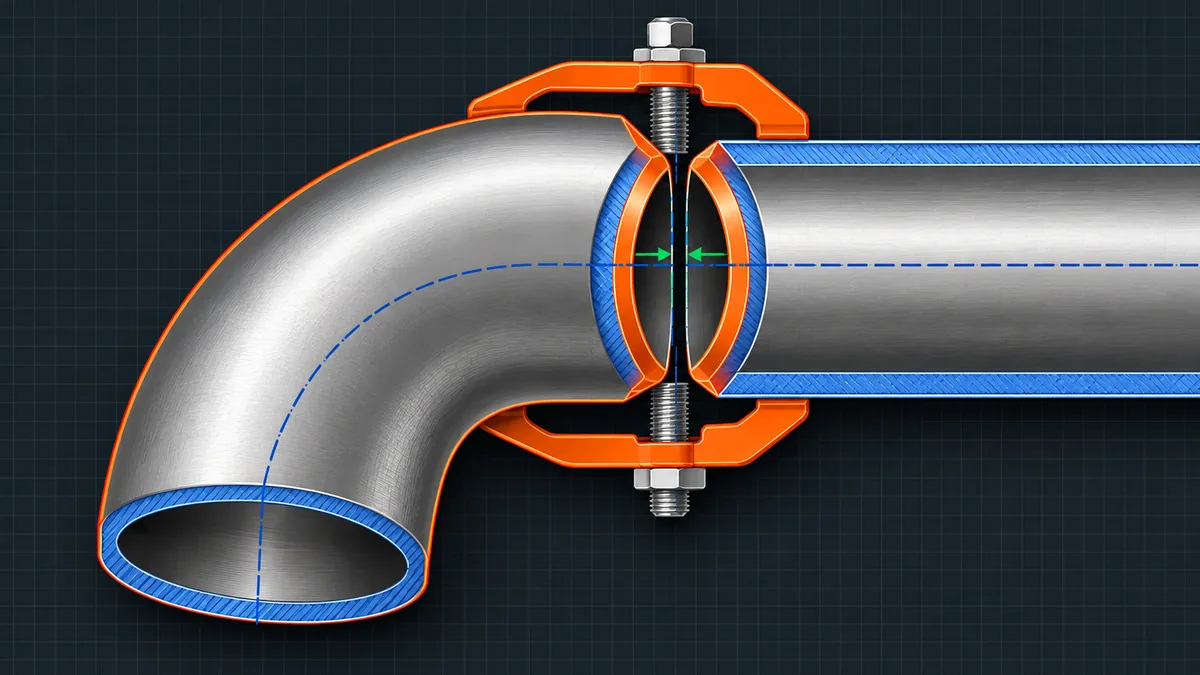
After welding, the butt weld is examined as the piping code requires, usually by radiography or ultrasonic testing. Our NDT method selection guide compares the methods and shows when each is the better fit.
How Are B16.9 Fittings Proven and Tested?
B16.9 does not require a hydrostatic test of each production fitting. Hydrostatic testing of wrought fittings is not required by the standard, but every fitting must withstand, without leakage or impairment, the hydrostatic test pressure the applicable piping code requires for seamless pipe of equivalent material and the marked size and wall.
What Is the Design Proof Test?
When a manufacturer chooses proof testing to qualify a design, the fitting is welded to pipe and tested with water. It must hold the computed pressure for at least 180 seconds without loss of containment, cracking or tearing. The minimum proof test pressure is computed from the fitting’s actual tensile strength.
This is a qualification pressure for the design, not an operating or system test pressure. To estimate pipe burst pressure from tensile strength, you can use our burst pressure calculator.
How Far Does One Proof Test Carry?
One test fitting can qualify similar fittings across a size range of one-half to twice the tested size, and across t/D ratios from one-half to three times the tested value. Materials in the same Table 5-1 group are covered because capacity scales with tensile strength. The test report must be certified by the manufacturer and by a licensed Authorized Inspector or another third party with relevant experience.
The finished piping system is tested under the piping code, not under B16.9. For when to use liquid or gas, see our guide to hydrostatic versus pneumatic pressure testing.
How Do You Order and Inspect B16.9 Fittings?
An order for B16.9 fittings must state more than the size. Specify the NPS, the wall thickness or schedule at the weld ends, the material specification and grade with the WP prefix, the fitting type and radius, the end preparation and any special requirements such as inside diameter control or inspection documents.
How Do You Verify a B16.9 Fitting on Receipt?
- Check the marking. Confirm the manufacturer mark, the grade with the WP prefix, the NPS and the schedule or wall thickness against the purchase order.
- Match the certificate. Compare the material test certificate with the marking, including heat number, grade, chemistry, mechanical properties and heat treatment.
- Verify the dimensions. Measure center-to-end, outside diameter at bevel and end thickness against the B16.9 tables and tolerances.
- Inspect the weld ends. Check bevel angle, root face and surface condition, and look for laminations, cracks, arc strikes or damage from handling.
- Confirm the wall at the joint. Compare the end wall with the pipe it will join so that the mismatch stays inside the allowed envelope and the WPS limits.
- Record and release. Log heat numbers for traceability, tag accepted items and quarantine nonconforming fittings until the purchaser decides.
Many projects add a client or third-party inspector at the supplier or at receiving. Our guide to third party inspection in welding explains what that role covers and how it differs from the manufacturer’s own quality system.
Quick Reference: ASME B16.9 Numbers at a Glance
This cheat sheet collects the values used most often when specifying and inspecting fittings. Verify each against the B16.9 edition in your contract.
| Parameter | Value | Basis |
|---|---|---|
| Size range | NPS 1/2 to 48 (DN 15 to 1200) | Section 1 |
| Long radius elbow, A | 1.5 x NPS (NPS 6 = 229 mm) | Table 6.1-1 |
| Short radius elbow, A | 1.0 x NPS (NPS 6 = 152 mm) | Table 6.1-4 |
| 3D radius elbow, A | 3.0 x NPS (NPS 6 = 457 mm) | Table 6.1-6 |
| Pressure rating basis | Matching seamless pipe, no Class | Section 2 |
| Compliance marking | WP prefix in grade, for example WPB | Section 4 |
| Minimum wall | 87.5% of nominal unless specified | Table 11-1 and Figure 8-1 |
| Plain bevel range | x to 22 mm; compound above 22 mm | Table 8-1 |
| Center-to-end tolerance | +/- 2 mm up to NPS 24 | Table 11-1 |
| Proof test | 180 s hold; f = 1.10, 1.05 or 1.0 | Section 9 |
| Production hydrostatic test | Not required by B16.9 | Section 10 |
| Permitted material specifications | A234, A403, A420, A815, B361, B363, B366 | Section 5 |
What Are the Common Mistakes and Limits?
Most fitting problems come from ordering errors and dimension mix-ups rather than from the standard itself. The points below are the ones that most often cause rework or rejected deliveries.
- Ordering by size only. The marking must show a schedule or wall thickness, and that wall must suit the pipe it joins.
- Looking for a Class rating. Fittings are rated as matching pipe. Flange Class and fitting wall are checked separately.
- Mixing SI and U.S. Customary values. The standard treats combining the two systems as nonconformance.
- Using long radius dimensions for other elbows. Short radius and 3D elbows have different A values.
- Treating field-cut or fabricated pieces as B16.9. Fabricated laterals are outside the standard, and a field-segmented elbow stops being a B16.9 product once cut.
- Assuming the standard approves the service. Selection of fitting type and material for a fluid service is the designer’s job under the piping code.
- Accepting special fittings as standard. A fitting with an S58, S8 or SPLD suffix has agreed dimensions, not standard ones.
Details here follow the 2018 edition text and the published scope of the 2024 edition. Always confirm clause numbers, tolerances and tables in the edition named in your purchase order, and follow the piping code for ratings, temperature limits and testing.
Frequently Asked Questions
What is ASME B16.9?
ASME B16.9 is the standard for factory-made wrought butt-weld fittings. It covers overall dimensions, tolerances, ratings, testing and markings for elbows, tees, reducers, caps and stub ends in sizes NPS 1/2 through NPS 48. It does not select fittings for a service or cover installation welding. The current edition is ASME B16.9-2024.
What sizes does ASME B16.9 cover?
ASME B16.9 covers NPS 1/2 through NPS 48, which corresponds to DN 15 through DN 1200. Fittings outside that range are not B16.9 fittings unless the manufacturer and purchaser agree on special dimensions. Fittings made to agreed dimensions carry a suffix in the grade marking, such as S58 for A234, A403 and A420 material. The standard also excludes fabricated laterals and other fittings made with circumferential or intersection welds.
What is the difference between ASME B16.9 and B16.11?
B16.9 covers butt-weld fittings that are welded end to end to pipe, while B16.11 covers forged socket-weld and threaded fittings. Butt-weld fittings are generally used on larger sizes and where full-penetration welds and smooth bores are needed. Socket-weld fittings are generally used on small-bore lines. Our guide to butt weld versus socket weld selection rules compares the two in detail.
How are B16.9 fittings pressure rated?
B16.9 fittings are not given a pressure Class. The allowable pressure is calculated as for straight seamless pipe of equivalent material and the wall thickness shown in the marking, using the applicable ASME B31 section. The pipe size, wall thickness or schedule number, and material identity on the fitting replace pressure rating marks. A fitting used under a code is also subject to that code’s temperature and low-temperature limits.
Are ASME B16.9 fittings hydrostatically tested?
The standard does not require a hydrostatic test of each production fitting. Every fitting must be capable of withstanding the hydrostatic test pressure that the piping code requires for matching seamless pipe. Manufacturers qualify designs by mathematical analysis, proof testing or detailed stress analysis. A proof test holds the computed pressure for at least 180 seconds.
What does WP mean in a marking such as WPB?
The prefix WP in the material grade designation certifies that the fitting was manufactured to ASME B16.9, including all dimensional requirements. In WPB, the B identifies the carbon steel grade in ASTM A234. Special fittings made to agreed dimensions use a suffix instead, such as S58, S8 or SPLD. The marking also shows the manufacturer, size and schedule or wall thickness.
What is the difference between long radius, short radius and 3D elbows?
The three elbow types differ in bend radius. A long radius elbow uses 1.5 times NPS, a short radius elbow uses 1.0 times NPS and a 3D radius elbow uses 3.0 times NPS. For NPS 6, the 90-degree center-to-end dimension is 229 mm for long radius, 152 mm for short radius and 457 mm for 3D radius. Long radius is the common default because it gives lower flow resistance than a short radius elbow.
Key Terms
- NPS (nominal pipe size)
- The dimensionless size designation used for pipe and fittings, related to the metric DN size.
- Long radius elbow
- An elbow with a centerline bend radius of 1.5 times the nominal pipe size.
- WP prefix
- The mark in the material grade designation that certifies a fitting meets the standard dimensions of B16.9.
- Schedule
- A dimensionless number that designates a group of standard pipe wall thicknesses, defined in ASME B36.10M and B36.19M.
- Root face
- The flat land left at the root of a weld bevel, which controls fit-up and root penetration.
- Material test certificate (MTC)
- The manufacturer’s document that reports a heat’s chemistry and mechanical test results.
- Design proof test
- A water test of a representative fitting welded to pipe, used to qualify a fitting design under section 9.
Conclusion
ASME B16.9 fittings are the standard dimensional language of butt-weld piping. Remember the anchor points: NPS 1/2 to 48 scope, a rating that follows the matching pipe, the WP marking, the 87.5% minimum wall, the 37.5 degree typical bevel, and the fact that no production hydrostatic test is required. Treat the standard as the dimensional and marking baseline, then let the piping code decide ratings, temperature limits and examination. Always work from the edition named in your contract, and check the flange Class separately. As a next step, use our ASME B16.5 flange pressure-temperature rating calculator to check the flange at the other end of your fitting run.
This guide was prepared by the WeldFabWorld technical team from the standards listed in Standards and References. Verify every requirement against the code edition and specification applicable to your project.
Standards and References
- ASME B16.9, Factory-Made Wrought Buttwelding Fittings (2024 edition; 2018 edition text consulted), ASME
- ASME B16.25, Buttwelding Ends, ASME
- ASME B16.5, Pipe Flanges and Flanged Fittings: NPS 1/2 Through NPS 24 Metric/Inch Standard, ASME
- ASME B31.3, Process Piping, and ASME B31.1, Power Piping, ASME
- ASME B36.10M, Welded and Seamless Wrought Steel Pipe, and ASME B36.19M, Stainless Steel Pipe, ASME
- ASTM A234/A234M, A403/A403M, A420/A420M, A815/A815M and A960/A960M, ASTM International
- ASTM B361, B363 and B366 wrought fitting specifications, ASTM International
- ASME Boiler and Pressure Vessel Code, Section II, Materials, and Section VIII Division 2, ASME
- MSS SP-43 and MSS SP-75, Manufacturers Standardization Society