API 650 Tank Welding Requirements: Procedures, Joints and Inspection
Last updated:
API 650 tank welding decides whether a welded steel storage tank holds liquid safely for decades or leaks at its first fill. A large tank contains hundreds of metres of seam, and every joint must follow the same qualified procedures, joint details and examination rules. This guide explains those rules in the order an inspector meets them.
Quick answer: API 650 tank welding means joining tank shells, bottoms and roofs with welding procedures and welders qualified to ASME Section IX, using the joint details in API 650. Welds are then examined visually and by radiographic, ultrasonic, magnetic particle or penetrant methods, bottom seams are vacuum tested, and the finished tank is filled with water for a hydrostatic test.
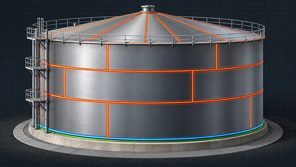
The standard uses full-penetration butt joints on the shell, lap-welded fillets on the bottom and roof, and a continuous fillet at the shell-to-bottom corner. These match the basic welding joint types used across fabrication, and the details are shown on drawings with standard welding symbols.
Requirements vary by edition and by the purchaser’s specification. Use this guide to orient yourself, then confirm every value in the standard named in your contract.
Key takeaways
- API 650 requires welding procedures and welders to be qualified under ASME BPVC Section IX, with added tank-specific rules in API 650 Section 9.
- Shell vertical and horizontal seams are full-penetration, full-fusion butt joints, and bottom and roof plates are lap welded with fillet welds.
- Spot radiography is sampled by length: first 3 m, then each additional 30 m of vertical joint or 60 m of horizontal joint, and shell butt joints in plate over 25 mm (1 in.) are fully radiographed.
- Bottom seams are leak tested by vacuum box or tracer gas, and the completed tank is hydrostatically tested.
- The contract edition and purchaser specification can add requirements beyond the minimums in the standard.
What Is API 650 Tank Welding?
API 650 tank welding is the qualified welding work that joins steel plates into leak-tight vertical storage tank shells, bottoms and roofs under API Standard 650.
API Standard 650 (API 650), Welded Tanks for Oil Storage, is published by the American Petroleum Institute (API). It sets minimum requirements for material, design, fabrication, erection and inspection of vertical, cylindrical, aboveground, closed- and open-top welded tanks. These tanks hold liquids at internal pressures close to atmospheric, meaning pressure that does not exceed the weight of the roof plates, and higher pressures are allowed only when additional requirements are met.
The standard applies to tanks whose entire bottom is uniformly supported and to non-refrigerated service with a maximum design temperature of 93 °C (200 °F). Its basis is an internal pressure of not more than 17.2 kPa (2.5 psig) gauge. Annexes extend the rules to elevated temperatures, small internal pressures, stainless steel, duplex stainless steel and aluminium tanks.
The current published edition is the 14th Edition (2025), although many contracts still cite the 13th Edition (2020) or an earlier edition with its addenda. The edition named in the purchase order controls the weld sizes, tolerances and examination rules for the job.
API 650 versus API 653. API 650 governs new tank construction. Inspection, repair, alteration and reconstruction of tanks already in service fall under API Standard 653 (API 653). More code explainers are collected in the ASME codes and standards guides on WeldFabWorld.
Where do the welding rules sit in API 650?
Welding requirements are spread across several sections of the standard rather than collected in one place. The table maps each section to its welding content.
| Section | Title | Welding content |
|---|---|---|
| 4 | Materials | Plate groups and material limits that drive procedure qualification and toughness needs |
| 5 | Design | Weld joint types, weld sizes and restrictions on joints for shell, bottom and roof |
| 6 | Fabrication | Shop fabrication, plate preparation and shop inspection |
| 7 | Erection | Field welding details, fit-up tolerances, inspection, testing and repairs |
| 8 | Methods of Inspecting Joints | Radiographic, magnetic particle, ultrasonic, liquid penetrant, visual and vacuum examination |
| 9 | Welding Procedure and Welder Qualifications | Qualification rules that build on ASME Section IX |
Which Welding Processes Does API 650 Allow?
API 650 allows tanks to be welded by shielded metal arc welding (SMAW), gas metal arc welding (GMAW), flux-cored arc welding (FCAW), gas tungsten arc welding (GTAW) and submerged arc welding (SAW), using suitable equipment and qualified procedures. Electrogas welding (EGW) and electroslag welding (ESW) are also named in the standard for suitable applications, subject to additional conditions. The purchaser may restrict the processes for a given contract.
In practice, the choice follows the joint and the working position. The table summarises typical field and shop practice.
| Process | Typical tank use | Practical notes |
|---|---|---|
| SMAW | Bottom lap seams, nozzle and attachment welds, tack welds, repairs | Low-hydrogen electrodes limit hydrogen; electrodes must be stored dry |
| SAW | Horizontal shell seams, bottom plate seams, annular plates | High deposition rate; best in the flat or horizontal position; flux handling must be controlled |
| FCAW / GMAW | Vertical shell seams, roof plates, general fabrication | Productive and all-position with suitable wire; shielding gas needs wind protection outdoors |
| GTAW | Root passes, thin sections, stainless and duplex tanks | Precise control, slow deposition |
| EGW | Vertical seams in thicker shell plate | Single-pass vertical process that needs specialised equipment and qualification |
Each process has its own technical guide. Read about shielded metal arc welding (SMAW) for manual seams, submerged arc welding (SAW) setup for mechanised shell seams, gas metal arc welding for wire-fed work, and TIG and GTAW fundamentals for root and stainless work.

How are electrodes and filler metals selected?
The filler metal must match the strength of the plate and suit the qualified welding procedure specification (WPS). Low-hydrogen electrodes, such as the E7018 class, are the usual choice for manual welding of carbon steel tank plate because they limit diffusible hydrogen and the risk of hydrogen cracking. Consumable storage and handling must follow the manufacturer’s instructions and the project specification.
Reading a WPS is easier when the electrode classification is clear. The guide to welding consumable nomenclature explains how to decode strength, coating and position designators.
How Are Welding Procedures and Welders Qualified?
API 650 requires every welding procedure and every welder to be qualified under ASME BPVC Section IX, with Section 9 of API 650 adding rules specific to tanks. The manufacturer or erector carries out the qualification, and the records stay available for the purchaser’s inspector.
What does procedure qualification involve?
A welding procedure specification (WPS) records the variables a welder must follow, and a procedure qualification record (PQR) documents the test weld that proves the procedure. The test weld is cut into specimens for tensile and bend testing and, when required, impact testing. Results must meet the limits of Section IX and API 650. The overview of mechanical testing of welds shows how these tests are carried out.
Material grouping decides how far one PQR can be extended. Section IX uses P-Numbers, Group Numbers and F-Numbers to define which plates and filler metals a qualification covers, and the guide to P-Numbers, Group Numbers and F-Numbers explains the system. Charpy impact testing of the procedure may also be required where the plate group and the design metal temperature call for toughness.
What is required of the welders?
Welders and welding operators must pass a Section IX performance qualification for the process, position and thickness range they will use. API 650 requires each welder to carry an identifying number, letter or symbol, and the erector keeps records that link welders to the welds they made. This identification supports repairs, because the weld map shows who made a rejected weld.
| Document | Purpose | Who holds it |
|---|---|---|
| WPS | States the variables for production welding | Manufacturer or erector |
| PQR | Proves the procedure with test results | Manufacturer or erector |
| Welder qualification record | Shows the welder passed the test for process, position and thickness | Manufacturer or erector |
Section IX is published by the American Society of Mechanical Engineers (ASME). Always apply the edition cited in the contract.
What Weld Joints Does API 650 Specify for the Shell, Bottom and Roof?
API 650 specifies full-penetration, full-fusion butt joints for shell vertical and horizontal seams, lap-welded fillet joints for most bottom plates, and a continuous fillet weld on both sides of the shell at the shell-to-bottom corner. Roof plates are lap welded with a continuous fillet weld on the top side. Joint dimensions and weld sizes appear in the Section 5 figures of the standard.
| Component | Typical joint | Key points |
|---|---|---|
| Shell vertical joints | Butt joint, complete penetration and fusion | Offset between adjacent courses of at least 5t, where t is the thicker plate |
| Shell horizontal joints | Butt joint, complete penetration and fusion | Alignment of the upper plate is limited (see the fit-up section below) |
| Shell-to-bottom joint | Continuous fillet on each side of the shell | Size set by shell thickness, with a maximum of 13 mm (1/2 in.) |
| Bottom plate seams | Lap joint with fillet on the top side | Three-plate laps kept at least 300 mm (12 in.) from each other and from the shell |
| Annular bottom plates | Butt-welded radial joints | Used where the standard requires annular plates under the shell |
| Roof plates | Lap joint with continuous fillet on top | Roof-to-top-angle joint also welded on the top side |
Drawings show these joints with standard weld symbols, and the weld map for the tank references the same joint numbers.
Why are vertical shell joints offset?
Vertical joints in adjacent shell courses must be offset by at least five times the plate thickness (5t) of the thicker course. The offset avoids stacking weld intersections in one vertical line, where residual stress and defects would otherwise concentrate.
What controls the shell-to-bottom joint?
The shell-to-bottom joint is a critical detail because shell bending and foundation settlement load this corner. API 650 specifies a continuous fillet weld on each side of the shell plate, sized from a minimum set by shell thickness up to a maximum of 13 mm (1/2 in.). Inspectors review this weld closely, and it receives specified examination and leak testing.
To estimate the filler metal for fillet seams such as this one, use the fillet weld consumable calculator.
What Fit-Up and Weld Quality Limits Apply?
API 650 limits plate misalignment at joints, the height of weld reinforcement, and the depth of undercut, and it requires welds to be free of cracks and to blend smoothly into the base metal. These limits are checked at fit-up and again at visual examination.
What misalignment is allowed?
| Joint and plate thickness | Maximum misalignment |
|---|---|
| Vertical joint, plate over 16 mm (5/8 in.) | 10 percent of plate thickness, not more than 3 mm (1/8 in.) |
| Vertical joint, plate up to 16 mm (5/8 in.) | 1.5 mm (1/16 in.) |
| Horizontal joint, upper plate over 8 mm (5/16 in.) | Upper plate may not project beyond the lower plate face by more than 20 percent of its thickness, with a maximum of 3 mm (1/8 in.) |
| Horizontal joint, upper plate up to 8 mm (5/16 in.) | 1.5 mm (1/16 in.) |
How high can weld reinforcement be, and how much undercut is acceptable?
Weld reinforcement on shell butt joints is limited by plate thickness and joint direction. Undercut limits are tight: 0.4 mm (1/64 in.) for vertical joints and 0.8 mm (1/32 in.) for horizontal joints.
| Plate thickness | Vertical joints | Horizontal joints |
|---|---|---|
| Up to 13 mm (1/2 in.) | 2.5 mm (3/32 in.) | 3 mm (1/8 in.) |
| Over 13 mm to 25 mm (1/2 in. to 1 in.) | 3 mm (1/8 in.) | 5 mm (3/16 in.) |
| Over 25 mm (1 in.) | 5 mm (3/16 in.) | 6 mm (1/4 in.) |
Visual examination also rejects crater cracks, other surface cracks and arc strikes in or next to a welded joint. Welds must be free of slag, and each pass must be cleaned before the next one is laid.
Scope note. Shell geometry tolerances such as plumbness, roundness, peaking and banding are controlled in the erection section of API 650. They affect weld quality indirectly, but they are not weld acceptance limits.
What Examination Does API 650 Require for Tank Welds?
API 650 requires visual examination of all welds and specifies radiographic examination (RT) of shell butt joints at defined frequencies. Magnetic particle (MT), liquid penetrant (PT) and ultrasonic (UT) methods are applied to specific joints or used as permitted alternatives. Section 8 of the standard sets the methods and acceptance rules.
How often are shell welds radiographed?
Spot radiography samples the shell butt joints by length. Vertical joints receive one spot radiograph in the first 3 m (10 ft) of each type and thickness for each welder, then one more for each additional 30 m (100 ft). Horizontal joints receive one spot in the first 3 m (10 ft) and one for each additional 60 m (200 ft). At least 25 percent of the vertical spots must fall at junctions of vertical and horizontal joints, with a minimum of two such intersections per tank.
Shell butt joints in plate thicker than 25 mm (1 in.) are radiographed completely, along with other joints that the standard designates. The radiographic technique follows ASME Section V, and acceptance follows the radiographic criteria of ASME Section VIII, Division 1, paragraph UW-51(b), as referenced by API 650. When a radiograph shows an unacceptable weld, the standard requires repair and additional radiography.
Worked example: how many spot radiographs?
The example counts spot radiographs for one thickness class of shell joint. It assumes a single welder and uses illustrative joint lengths. Real tanks are counted per thickness class and per welder, so actual totals are usually higher.
When are ultrasonic, magnetic particle and penetrant methods used?
Ultrasonic examination can replace radiography when the purchaser agrees and the requirements of Annex U are met. Magnetic particle or liquid penetrant examination is used on specified details such as the shell-to-bottom joint, with the stage of examination set by the edition and the contract. Stainless steel and duplex tanks commonly use liquid penetrant examination because magnetic particle methods do not suit austenitic material.
Visual examination applies to every weld and comes first, because it screens for surface defects before more costly methods are used. NDE personnel and procedures must be qualified to the requirements the contract names, and the {EXT(“https://www.api.org/”, “American Petroleum Institute (API)”)} publishes the standard that sets these rules.
How Are Completed Tank Welds Tested?
Completed tank welds are tested by vacuum box or tracer gas testing for bottom seams, pneumatic soap-film testing for shell reinforcing pads, low-pressure leak testing for roof seams, and hydrostatic testing of the filled tank. Each test targets a different leak path.
| Test | Applies to | Typical parameter |
|---|---|---|
| Vacuum box common | Bottom plate seams, shell-to-bottom joint | Partial vacuum of at least about 21 kPa (3 psi) with soap solution |
| Tracer gas alternative | Bottom seams where permitted | Per the qualified procedure |
| Pneumatic soap film | Shell reinforcing pad welds | 100 kPa (15 psig) air through the tell-tale hole |
| Roof leak test | Fixed roof seams | Low air pressure not exceeding the weight of the roof plates, or vacuum box |
| Hydrostatic test | Completed tank | Filled with water to the maximum design liquid level |
How does a vacuum box test work?
A vacuum box is a transparent-topped box that seals over a weld seam wetted with soap solution. A pump draws a partial vacuum, and any leak pulls air through the weld and forms bubbles. Inspectors overlap each box position so that every inch of the seam is examined.
What happens during the hydrostatic test?
The tank is filled with water to the maximum design liquid level, and the shell welds are examined visually for leaks during and after filling. Settlement of the foundation is usually monitored as the load rises. For stainless steel and duplex tanks, the chloride content of the test water is limited to protect the material, and the limit appears in the relevant annex.
Safety. Control the filling rate, keep vents clear and keep personnel away from the shell during the first fill. Repair welding on a filled tank requires a documented procedure and the purchaser’s approval.
How Is an API 650 Tank Welded and Verified, Step by Step?
An API 650 tank is welded and verified in eight steps that run from document review to the final records. The sequence below is a practical summary of the standard, not a replacement for it.
- Confirm the governing documents. Identify the API 650 edition and addenda named in the contract, the purchaser specification and the tank data sheet. These documents fix the weld sizes, examination scope and acceptance limits.
- Qualify procedures and welders. Qualify each WPS and every welder to ASME Section IX and API 650 Section 9. Record the results in PQRs and welder qualification records.
- Verify materials and consumables. Check plate heat numbers against material test certificates and confirm that electrodes, wires and fluxes match the WPS. Store and bake low-hydrogen consumables as specified.
- Fit up and tack weld. Align plates within the mismatch limits, set root gaps, clean the joint faces and apply qualified tack welds. Correct misalignment before welding begins.
- Weld in a controlled sequence. Weld to the WPS parameters, protect the arc from wind and moisture, clean each pass and back-gouge where required. Follow a sequence that limits distortion.
- Examine the welds. Perform visual examination, then radiographic or ultrasonic examination, and magnetic particle or penetrant examination where specified. Repair rejected areas and re-examine them.
- Test for leaks. Vacuum box or tracer gas test the bottom seams, pneumatically test reinforcing pads, test the roof seams, and hydrostatically test the filled tank.
- Compile the records. Assemble the weld map, welder identification, examination reports and test records into the final data book for the purchaser.
When Is Stress Relief or Special Material Welding Needed?
API 650 does not require general post weld heat treatment (PWHT) of tank shells, but it does require thermal stress relief of certain thick shell opening assemblies. Stainless steel, duplex stainless steel and aluminium tanks follow their own annexes with added welding controls.
When is thermal stress relief required?
Thermal stress relief applies to shell opening assemblies, such as large nozzles with reinforcing plates in thick shell courses, and to flush-type connections. The size and thickness thresholds are set in the standard. A typical stress relief holds the assembly at about 600 °C (1,100 °F) for roughly 1 hour per 25 mm (1 in.) of thickness. Use the PWHT soak time calculator to check hold times.
How are stainless steel and duplex tanks welded?
Annex S covers stainless steel tanks and Annex X covers duplex stainless steel tanks. Controls typically include limited heat input and interpass temperature, dedicated stainless tools to avoid carbon steel contamination, and cleaning after welding. Duplex weld metal also needs ferrite and austenite balance control. For background on these grades, see the guide to duplex stainless steels.
Field tip. Keep grinding discs, wire brushes and clamps for stainless work separate from carbon steel tools. Iron pickup from shared tools is a common cause of rust staining and pitting on finished stainless tanks.
Quick Reference: API 650 Welding Requirements at a Glance
The table condenses the main welding requirements into one reference. Values come from the sections above and must be confirmed against the edition and specification that apply to your project.
| Topic | Requirement summary | Where in API 650 |
|---|---|---|
| Procedure qualification | ASME Section IX plus API 650 additions | Section 9 |
| Welder qualification | Section IX; identification mark and records | Section 9 |
| Shell butt joints | Complete penetration and complete fusion | Section 5 |
| Vertical joint offset | At least 5t between adjacent courses | Section 5 |
| Shell-to-bottom joint | Continuous fillet each side, maximum 13 mm (1/2 in.) | Section 5 |
| Bottom seams | Lap joints; three-plate laps 300 mm (12 in.) apart | Section 5 |
| Vertical joint misalignment | 10 percent of thickness, max 3 mm (1/8 in.) over 16 mm plate; 1.5 mm (1/16 in.) up to 16 mm | Section 7 |
| Spot radiography | First 3 m then each 30 m (vertical); first 3 m then each 60 m (horizontal) | Section 8 |
| Full radiography | Shell butt joints in plate over 25 mm (1 in.) | Section 8 |
| Bottom leak test | Vacuum box, at least about 21 kPa (3 psi), or tracer gas | Sections 7 and 8 |
| Reinforcing pad test | 100 kPa (15 psig) air with soap film | Section 7 |
| Hydrostatic test | Water to maximum design liquid level | Section 7 |
| Thermal stress relief | Thick shell opening assemblies; about 600 deg C and 1 h per 25 mm | Section 5 |
Rule of thumb. Qualify first, fit up tight, weld to the WPS, examine by length-based sampling, and leak test every seam family before the water goes in. Anything not covered by the standard is decided by the purchaser specification.
What Are the Common Mistakes and Limitations?
Most API 650 welding problems come from skipping a control, not from missing knowledge. These are the mistakes inspectors meet most often.
- Counting spot radiographs for the whole tank at once instead of by joint type, thickness and welder.
- Leaving tack welds in vertical joints that are then welded by an automatic process, where the standard requires removal.
- Welding in wind, rain or on wet plate without shelter, which causes porosity and hydrogen problems.
- Using damp or unbaked low-hydrogen electrodes.
- Correcting misalignment after welding instead of before fit-up is accepted.
- Applying an old edition of API 650 when the contract names a newer one, or the reverse.
- Confusing API 650 new-construction rules with API 653 repair rules.
- Using high-chloride water to hydrotest stainless steel tanks.
- Failing to keep welder identification and the weld map complete.
What are the limits of this guide and of API 650?
API 650 is a purchase specification that sets minimum requirements for atmospheric storage tanks with uniformly supported bottoms. It does not cover refrigerated tanks or pressure vessels, and low-pressure tanks fall under API Standard 620 (API 620) or ASME pressure vessel codes instead.
Edition and specification. Requirements depend on the code edition and contract specification applicable to your project. Purchaser specifications, local regulations and owner standards often add examination or testing beyond the minimums. In India and the Gulf region, owner and EPC specifications commonly tighten the standard’s minimums, so check them before work starts.
Frequently Asked Questions
What does API 650 say about welding?
API 650 requires welding procedures and welders to be qualified under ASME Section IX, specifies the weld joint details for the shell, bottom and roof, and sets fit-up, reinforcement and undercut limits. It also defines the examination methods, including radiography and visual examination, and the leak tests for bottoms, reinforcing pads, roofs and the finished tank. Contract specifications and the edition named in the purchase order can add further requirements.
Does API 650 require post weld heat treatment (PWHT)?
API 650 does not require general PWHT of tank shells. It does require thermal stress relief of certain thick shell opening assemblies and flush-type connections above thresholds set in the standard. A typical stress relief holds the assembly at about 600 deg C (1,100 deg F) for roughly 1 hour per 25 mm (1 in.) of thickness. For hold-time arithmetic use the PWHT soak time calculator, and for the piping comparison see the guide to ASME B31.1 PWHT requirements.
How much radiography does an API 650 tank need?
Radiography is sampled by joint length. For shell vertical joints, one spot radiograph is taken in the first 3 m (10 ft) of each type and thickness per welder, then one more for each additional 30 m (100 ft). For horizontal joints the interval is one spot in the first 3 m (10 ft) and one for each additional 60 m (200 ft). Shell butt joints in plate thicker than 25 mm (1 in.) are radiographed completely.
Can ultrasonic testing replace radiography on an API 650 tank?
Ultrasonic examination (UT) can be used in place of radiography when the purchaser agrees and the requirements of API 650 Annex U are met. The UT procedure and personnel must be qualified, and the acceptance criteria come from the annex rather than from the radiographic rules. Many owners accept automated UT for thick shell plate, but the contract must say so. Without that agreement, radiography remains the default method.
Is a vacuum box test required for API 650 bottom welds?
Tank bottom welds must be leak tested, and vacuum box testing with a soap solution is the most common method. Tracer gas testing is an alternative where the standard and the purchaser allow it. A partial vacuum of at least about 21 kPa (3 psi) below atmospheric pressure is typical for vacuum box testing. Bubbles at a seam mark a leak that must be repaired and retested.
What is the difference between API 650 and API 653 for welding?
API 650 governs the welding of new tanks, including procedure qualification, joint details and examination. API Standard 653 (API 653) governs inspection, repair, alteration and reconstruction of tanks that are already in service. API 653 refers back to API 650 for new weld details and materials, while adding rules for repairs, hot taps and shell replacement. Use the standard that matches the tank’s life stage.
Which code qualifies welders for API 650 tank construction?
ASME BPVC Section IX is the qualification code named by API 650, together with the added requirements in API 650 Section 9. Each welder must be qualified for the process and position used, and must carry an identification mark linked to the weld records. Qualification to another code is accepted only where the standard or the purchaser allows it. Check the contract before assigning welders qualified to other systems.
Key Terms
- Welding procedure specification (WPS)
- A written document that lists the welding variables that production welders must follow.
- Procedure qualification record (PQR)
- A record of the test weld and test results that prove a WPS is sound.
- Shell course
- One horizontal ring of shell plates that forms a layer of the tank wall.
- Annular plate
- A thicker bottom plate placed under the shell to carry shell loads at the tank edge.
- Spot radiography
- Radiographic examination of selected short lengths of weld to sample overall quality.
- Vacuum box test
- A leak test that draws a partial vacuum over a soap-wetted weld seam to reveal bubbles at leaks.
- Hydrostatic test
- A test in which the completed tank is filled with water to the design liquid level to check tightness and strength.
Conclusion
API 650 tank welding comes down to four controls: qualified procedures and welders, the joint details and fit-up limits in the standard, length-based examination, and leak testing before the tank enters service. The shell butt joints, the shell-to-bottom fillet and the lap-welded bottom each have their own detail and their own examination or test. Following the sequence in this guide keeps those controls in the right order, and the quick reference table gives a fast check during inspection.
Edition and contract rules always take priority, so confirm the numbers against your project documents. As a next step, test your understanding of procedure and welder qualification with the ASME Section IX quiz, since Section IX underpins every qualification on an API 650 tank.
About This Guide
This guide was prepared by the WeldFabWorld technical team from the standards listed in the references below. Verify every requirement against the code edition and specification applicable to your project before relying on it.
Standards and References
- API Standard 650, Welded Tanks for Oil Storage, American Petroleum Institute (api.org).
- API Standard 653, Tank Inspection, Repair, Alteration, and Reconstruction, American Petroleum Institute.
- API Standard 620, Design and Construction of Large, Welded, Low-Pressure Storage Tanks, American Petroleum Institute.
- ASME Boiler and Pressure Vessel Code, Section IX, Welding, Brazing, and Fusing Qualifications, American Society of Mechanical Engineers (asme.org).
- ASME Boiler and Pressure Vessel Code, Section V, Nondestructive Examination, American Society of Mechanical Engineers.
- ASME Boiler and Pressure Vessel Code, Section VIII, Division 1, Rules for Construction of Pressure Vessels, American Society of Mechanical Engineers (paragraph UW-51 radiographic acceptance, referenced by API 650).