Flange Weight Calculator
Flange weight equals net volume multiplied by density. Add the disc, raised face and hub volumes, subtract the bore and bolt holes, then multiply by 7,850 kg/m³ for carbon steel. Enter your dimensions below, or use the Pipe Weight Calculator for the attached pipe run. More tools sit in the Fabrication & Calculators category.
Calculate Flange Weight
- Flange weight is geometry times density: disc plus raised face plus hub, minus bore and bolt holes.
- Take dimensions from the governing standard or the manufacturer drawing, not from memory.
- Density changes the answer by about 2 percent between carbon and austenitic stainless steel, and by almost two thirds for aluminium.
- Calculated weight is an estimate. Catalogue and weighed values differ because of fillets, chamfers and tolerances.
- Bolts, studs, nuts and gaskets are not part of flange weight.
- Pair this tool with the Elbow Weight Calculator to complete a piping take-off.
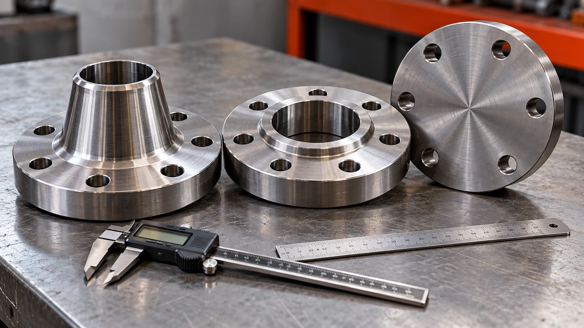
What Is a Flange Weight Calculator?
A flange weight calculator is a tool that estimates flange mass from its dimensions and material density.
Fabricators, estimators and store keepers need flange weight before any flange reaches the shop floor. It sets the crane or hoist rating, the freight cost, the skid design and the material cost per piece. Catalogue tables give weights for standard sizes, but a special flange, a flange with a modified hub or a flange in a non-standard alloy has no catalogue entry. Geometry solves that problem, because volume does not change with the supplier.
A flange is a ring, a hub and a set of drilled holes, so the maths is plain geometry. The calculator above applies the same equations you would write by hand, and it prints every step so you can check the arithmetic. For the standard dimensions of each style, the guide to flange types, face types, grades and gaskets explains what each part is called and where it sits.
How is flange weight found in one line?
Flange weight is found by adding the volumes of the disc, raised face and hub, subtracting the volumes of the bore and bolt holes, and multiplying the net volume by the material density. In SI units, volume in cubic millimetres is multiplied by 10-9 and then by density in kg/m³ to give kilograms.
How Do You Calculate Flange Weight?
Follow these six steps for any flange. They match the calculator and the HowTo markup on this page.
- Collect outside diameter D, bore d, thickness T, raised face diameter and height, hub diameters and length, and the bolt hole count and diameter.
- Calculate the annular disc volume from D, d and T.
- Add the raised face ring and the hub frustum, subtracting the bore that passes through the hub.
- Subtract the volume of every bolt hole, using the disc thickness as the hole length.
- Multiply the net volume by the material density to get mass.
- Convert to pounds by multiplying kilograms by 2.20462, then multiply by quantity.
The position of the holes is a drilling question, not a weight question. If you need coordinates for layout or marking, use the Flange Bolt Circle and Hole Pitch Calculator.
Worked Example: Weight of a Raised Face Flange
The numbers below are illustrative values chosen to show the method. They are not copied from any standard table. Click Load Worked Example in the calculator to see the same result.
The disc dominates the answer. In this example the hub adds about 10 percent of the disc volume, the raised face about 1 percent, and the eight bolt holes remove about 5 percent. A quick estimate from outside diameter, bore and thickness alone can therefore be off by ten percent or more on a weld neck flange, so use the full model whenever the hub is long.
How Do Flange Types Change the Weight?
The same formula covers every type. Only the inputs change. The table shows which features matter for each style.
| Type | Geometry that drives weight | Calculator inputs |
|---|---|---|
| Weld neck | Long tapered hub, bore matched to the pipe | All fields, hub diameters and length |
| Slip-on | Short hub, bore slightly larger than pipe outside diameter | Short hub length, same diameter at both ends |
| Socket weld | Socket counterbore, small hub | Use the main bore; the counterbore is a small correction |
| Lap joint | Plain disc with a radius at the bore, paired with a stub end | Disc only; leave the hub blank |
| Threaded | Threaded bore, short hub | Use the nominal bore |
| Blind | Solid disc with no bore and no hub | D, T, raised face, bolt holes |
Face type matters too. A raised face adds a small ring of metal. A flat face adds none. Ring-type joint faces carry a groove, which removes metal. The guide to flange weld symbols shows how the welded joint is drawn on the same flanges, and the welding joint types guide explains the groove and fillet joints that attach them to pipe.
Which Density Should You Use for a Flange?
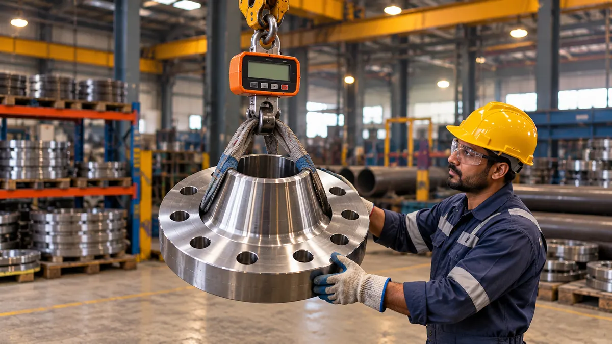
Use the density of the actual alloy on the material test certificate or the supplier datasheet. The table lists typical values that the calculator offers. Differences between grades inside one family are small, but they are not zero.
| Material | Typical density (kg/m³) | Note |
|---|---|---|
| Carbon and low alloy steel | 7,850 | Standard value for take-off |
| Austenitic stainless 304 / 316 | 8,000 | About 2 percent above carbon steel |
| Duplex stainless | 7,800 | Close to carbon steel; see the duplex stainless steel guide |
| Nickel alloy 625 | 8,440 | Heavier than stainless for the same shape |
| Aluminium | 2,700 | About one third of steel |
When the part is cast or forged, a heat-specific density is rarely needed. A one percent density error gives a one percent weight error, which is smaller than the geometry error from a missed fillet or chamfer.
How Accurate Is a Calculated Flange Weight?
A calculated flange weight is an estimate, normally within a few percent of the real part when the dimensions come from the drawing. The model uses sharp corners, a straight bore and a straight-sided hub taper. Real flanges have corner radii, hub fillets, bevelled weld ends and machining allowance. Tolerances on thickness and diameter also move the result.
Do not use a calculated weight for a certified lifting plan, a weighbridge cross-check or a contractual weight declaration unless the figure has been confirmed against the manufacturer’s data or a scale. Dimensions in a standard also change by edition, so confirm the edition named in your purchase order or specification.
A scale reading beats a calculation for any piece you will lift. Use the calculator for planning, and keep the weighed value for the record. The same discipline applies to incoming goods, and the incoming material checking rules explain what to verify at the gate.
Where Is Flange Weight Used in Fabrication?
- Material take-off. Total tonnage of flanges per line or per spool feeds purchase orders and cost reports. Add the pipe with a pipe weight estimator and fittings through elbow weights.
- Lifting and handling. Rigging for a heavy spool or a vessel nozzle with a large flange starts from weight.
- Freight and packing. Skid loads, container limits and pallet counts are weight limited more often than volume limited.
- Vessel weight. Nozzle flanges add to empty weight in a vessel weight summary. Dish end mass is covered in the hemispherical dish end weight calculator.
- Pressure rating checks. Weight does not set rating, but the class and temperature do. Look those up with the ASME B16.5 flange pressure and temperature rating calculator.
- Pipe class decisions. Wall thickness choice is separate from flange choice, and the Schedule 40 versus Schedule 80 pipe comparison helps with the matching weld end.
What Are the Common Mistakes When Calculating Flange Weight?
- Mixing units. Entering inches and reading millimetres, or the reverse. Pick the unit first.
- Counting the raised face twice. If the thickness you have already includes the raised face, leave the raised face fields blank.
- Using the pipe outside diameter as the bore. A weld neck bore follows the pipe inside diameter, while a slip-on bore follows the pipe outside diameter.
- Forgetting the bolt holes. Eight large holes in a heavy flange remove a few percent of mass.
- Adding bolts and gaskets. Fasteners and gaskets are separate line items.
- Quoting a standard edition from memory. Dimensions can change between editions, so confirm against the edition in your contract.
- Applying a stainless density to a carbon steel flange. The error is small, but it compounds across hundreds of pieces.
Quick Reference: Flange Weight Cheat Sheet
| Item | Formula or value |
|---|---|
| Annular disc volume | (π/4) x (D² – d²) x T |
| Raised face ring volume | (π/4) x (Drf² – d²) x hrf |
| Hub volume | (πL/12) x (Hb² + HbHt + Ht²) – (π/4) x d² x L |
| Bolt hole volume | n x (π/4) x h² x T |
| Mass in kg | V in mm³ x 10-9 x density in kg/m³ |
| Kilograms to pounds | kg x 2.20462 |
| Inches to millimetres | in x 25.4 |
| Blind flange | Set d = 0, no hub |
Key Terms
- Outside diameter (D)
- The largest diameter of the flange disc, measured across the rim.
- Bore (d)
- The central hole through the flange that matches the pipe.
- Raised face
- A thin circular boss on the flange face that concentrates gasket load.
- Hub
- The tapered or straight collar behind the disc that joins the flange to the pipe.
- Bolt circle
- The circle on which the bolt hole centres sit.
- Density
- The mass of a material per unit volume, in kg/m³.
- Net volume
- The metal volume left after the bore and bolt holes are removed.
Standards and References
- ASME B16.5, Pipe Flanges and Flanged Fittings: NPS 1/2 Through NPS 24 Metric/Inch Standard, issued by ASME.
- ASME B16.47, Large Diameter Steel Flanges: NPS 26 Through NPS 60 Metric/Inch Standard, issued by ASME.
- ASME B31.3, Process Piping, issued by ASME.
- EN 1092-1, Flanges and their joints: Circular flanges for pipes, valves, fittings and accessories, issued by CEN.
Verify all dimensions and the edition against the standard named in your specification. Standards are copyrighted, and this page does not reproduce their dimension tables.
Frequently Asked Questions
How do you calculate flange weight?
Add the volumes of the flange disc, raised face and hub, subtract the bore and bolt holes, then multiply the net volume by the material density. For carbon steel the density is about 7,850 kg/m3. Multiply kilograms by 2.20462 to get pounds.
What density should I use for a stainless steel flange?
Use about 8,000 kg/m3 for austenitic grades such as 304 and 316, or the value on the material certificate. Duplex stainless is close to 7,800 kg/m3, which is nearly the same as carbon steel.
Does flange weight include bolts and gaskets?
No. Flange weight covers the metal of the flange only. Studs, nuts and gaskets are separate line items in a take-off, and their mass depends on bolt size, length and gasket type.
Why does a calculated weight differ from the catalogue weight?
Catalogues use the real shape, with corner radii, hub fillets, bevelled weld ends and tolerances. A calculation uses sharp corners and a straight hub taper, so the two values normally differ by a few percent.
Can this calculator weigh a blind flange?
Yes. Choose Blind as the flange type. The bore and hub fields are switched off, and the weight comes from the solid disc, any raised face and the bolt holes.
Does the raised face count toward flange weight?
Yes, if the raised face is separate from the thickness you entered. Enter the raised face diameter and height to include it. Leave both blank when the thickness already includes the raised face.
Where do standard flange dimensions come from?
Dimensions come from the governing standard, such as ASME B16.5 for NPS 1/2 to NPS 24, ASME B16.47 for large diameters, or EN 1092-1. This page does not copy those tables, so read the values from your edition of the standard.
Conclusion
Flange weight comes from simple geometry: disc plus raised face plus hub, minus the bore and bolt holes, multiplied by density. Take dimensions from the standard or the drawing, pick the right density, and treat the answer as a planning estimate until a scale confirms it. The calculator above handles every common flange style and prints each step. For your next step, add the attached pipe run to the take-off with the pipe weight calculator on this site, then browse the full set of fabrication calculation tools on the hub page.